wiring AUDI A4 1995 B5 / 1.G ATQ Engine Motronic Injection System Servicing Workshop Manual
[x] Cancel search | Manufacturer: AUDI, Model Year: 1995, Model line: A4, Model: AUDI A4 1995 B5 / 1.GPages: 78, PDF Size: 1 MB
Page 19 of 78
24-17
Wire and component test using
VAG1598/31 test box
Notes:
VAG1598/31 test box is designed so that it can
be simultaneously connected to the wiring
harness at the Engine Control Module (ECM)
and also to the ECM itself.
This is advantageous because electronic
engine control remains fully functional (e.g.
measurement of signals with engine running)
when the test box is attached.
Relevant test procedures note whether Engine
Control Module (ECM) should also be
connected to the test box or not.
Always use VAG1594A connector test kit to
attach measurement devices (e.g. VAG1527B
voltage tester, VAG1526 multimeter etc.).
CAUTION!
To reduce the risk of damaging electronic
components, set the tester to the approprate
test range and observe test requirements
before connecting test leads.
Pa
ge 19 of 78 Motronic in
jection s
ystem, servicin
g
11/23/2002 htt
p://127.0.0.1:8080/audi/servlet/Dis
play?action=Goto&t
yp
e=re
pair&id=AUDI.B5.FU05.24.1
Page 22 of 78
24-20
Important note:
After re-connecting the Engine Control Module (ECM), the following work
steps must be performed:
- Check DTC memory and erase it if necessary Page 01
-15
.
- Perform adaptation of the Throttle Valve Control Module -J338- Page
24
-142
.
Note:
In the first adaptation phase during engine basic setting, it is possible that
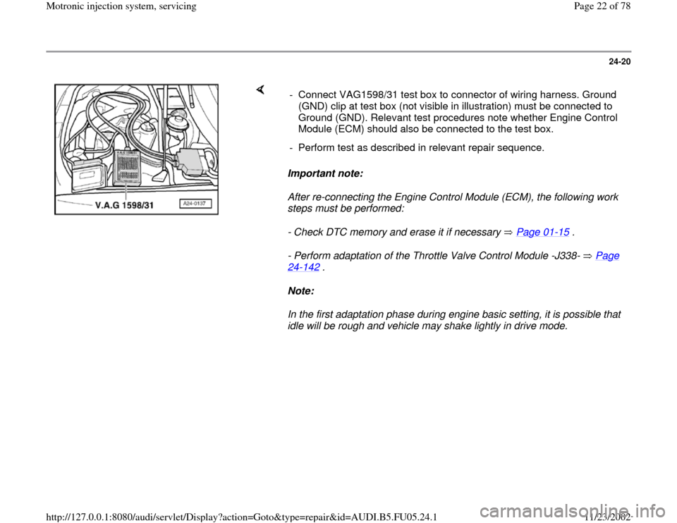
idle will be rough and vehicle may shake lightly in drive mode. - Connect VAG1598/31 test box to connector of wiring harness. Ground
(GND) clip at test box (not visible in illustration) must be connected to
Ground (GND). Relevant test procedures note whether Engine Control
Module (ECM) should also be connected to the test box.
- Perform test as described in relevant repair sequence.
Pa
ge 22 of 78 Motronic in
jection s
ystem, servicin
g
11/23/2002 htt
p://127.0.0.1:8080/audi/servlet/Dis
play?action=Goto&t
yp
e=re
pair&id=AUDI.B5.FU05.24.1
Page 45 of 78
24-38
Checking voltage supply
Test requirements:
Fuel Pump (FP) OK, checking Page 24
-
49
.
Fuse for fuel injectors OK
Electrical Wiring Diagrams, Troubleshooting &
Component Locations binder
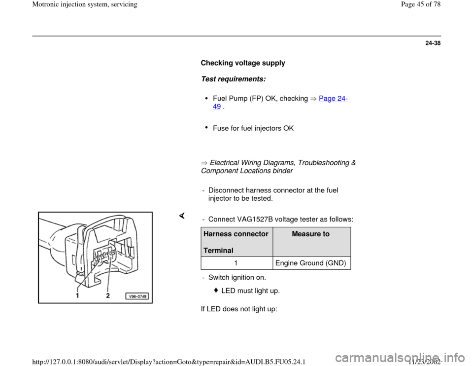
- Disconnect harness connector at the fuel
injector to be tested.
If LED does not light up: - Connect VAG1527B voltage tester as follows:Harness connector
Terminal
Measure to
1 Engine Ground (GND)
- Switch ignition on.
LED must light up.
Pa
ge 45 of 78 Motronic in
jection s
ystem, servicin
g
11/23/2002 htt
p://127.0.0.1:8080/audi/servlet/Dis
play?action=Goto&t
yp
e=re
pair&id=AUDI.B5.FU05.24.1
Page 46 of 78
Electrical Wiring Diagrams, Troubleshooting & Component Locations
binder - Check wire connection between terminal 1 and fuse for injector valves
for open circuit:
Pa
ge 46 of 78 Motronic in
jection s
ystem, servicin
g
11/23/2002 htt
p://127.0.0.1:8080/audi/servlet/Dis
play?action=Goto&t
yp
e=re
pair&id=AUDI.B5.FU05.24.1
Page 48 of 78
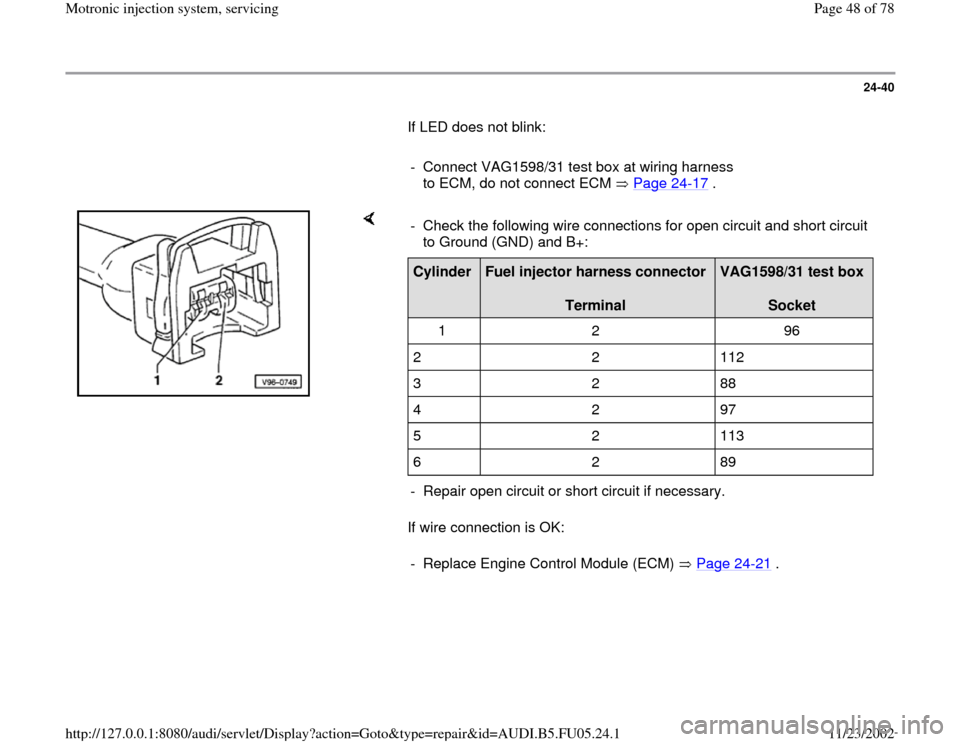
24-40
If LED does not blink:
- Connect VAG1598/31 test box at wiring harness
to ECM, do not connect ECM Page 24
-17
.
If wire connection is OK: - Check the following wire connections for open circuit and short circuit
to Ground (GND) and B+: Cylinder
Fuel injector harness connector
Terminal
VAG1598/31 test box
Socket
1 2 96
2 2 112
3 2 88
4 2 97
5 2 113
6 2 89
- Repair open circuit or short circuit if necessary.
- Replace Engine Control Module (ECM) Page 24
-21
.
Pa
ge 48 of 78 Motronic in
jection s
ystem, servicin
g
11/23/2002 htt
p://127.0.0.1:8080/audi/servlet/Dis
play?action=Goto&t
yp
e=re
pair&id=AUDI.B5.FU05.24.1
Page 55 of 78
24-46
Test requirement:
Fuel pressure OK, checking Page 24
-30
.
Test sequence
- Remove fuel distributor including fuel injectors
from intake manifold Page 24
-43
. Fuel lines
remain connected.
- Connect VAG1598/31 test box at wiring harness
to ECM, do not connect ECM Page 24
-17
.
- Bridge terminals 1 and 65 at test box using
adapter cables from VAG1594A connector test
kit (this step supplies Ground -GND- to one side
of relay coil for Fuel Pump -FP- relay).
Note:
Fuel Pump (FP) relay is supplied with B+ via the
central electric (terminal 30). Fuel Pump (FP)
relay receives minus via the cable bridge in test
box. The Fuel Pump (FP) is now running
constantly.
Pa
ge 55 of 78 Motronic in
jection s
ystem, servicin
g
11/23/2002 htt
p://127.0.0.1:8080/audi/servlet/Dis
play?action=Goto&t
yp
e=re
pair&id=AUDI.B5.FU05.24.1
Page 62 of 78
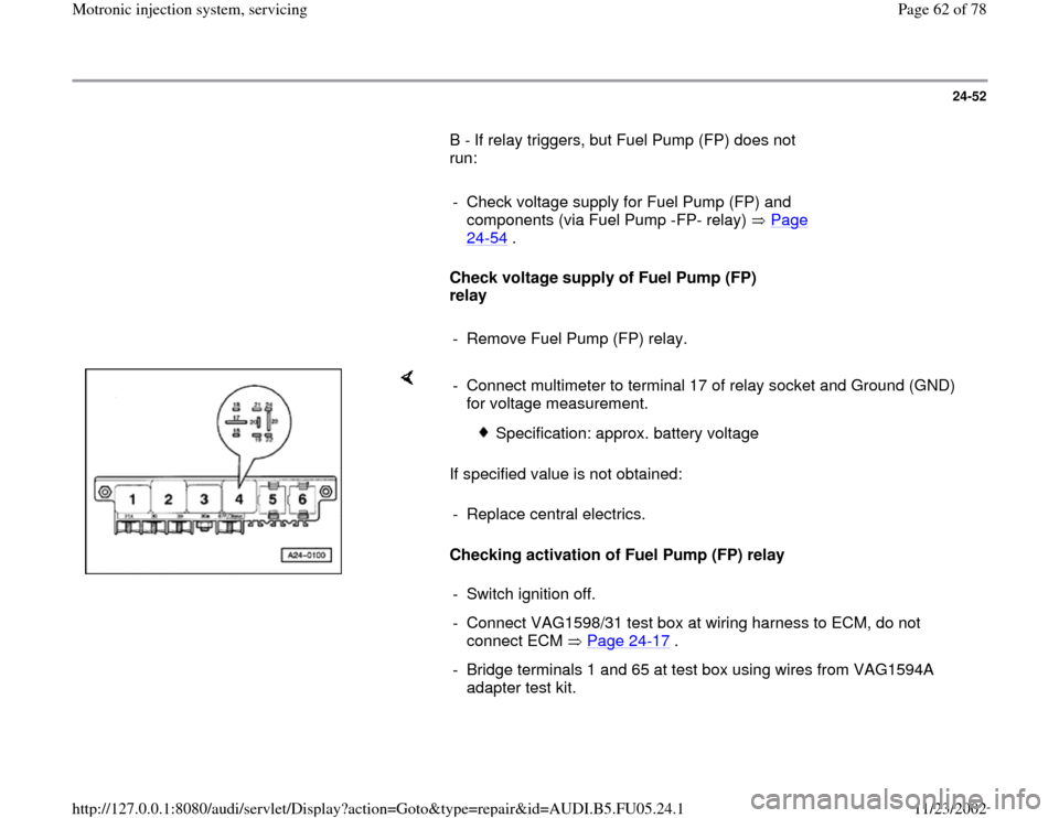
24-52
B - If relay triggers, but Fuel Pump (FP) does not
run:
- Check voltage supply for Fuel Pump (FP) and
components (via Fuel Pump -FP- relay) Page
24
-54
.
Check voltage supply of Fuel Pump (FP)
relay
- Remove Fuel Pump (FP) relay.
If specified value is not obtained:
Checking activation of Fuel Pump (FP) relay - Connect multimeter to terminal 17 of relay socket and Ground (GND)
for voltage measurement.
Specification: approx. battery voltage
- Replace central electrics.
- Switch ignition off.
- Connect VAG1598/31 test box at wiring harness to ECM, do not
connect ECM Page 24
-17
.
- Bridge terminals 1 and 65 at test box using wires from VAG1594A
adapter test kit.
Pa
ge 62 of 78 Motronic in
jection s
ystem, servicin
g
11/23/2002 htt
p://127.0.0.1:8080/audi/servlet/Dis
play?action=Goto&t
yp
e=re
pair&id=AUDI.B5.FU05.24.1
Page 63 of 78
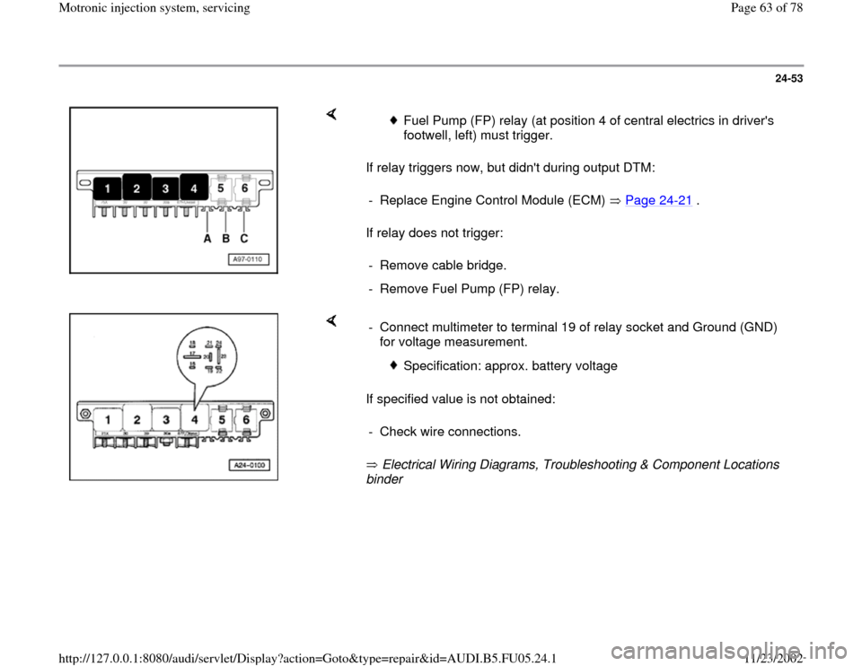
24-53
If relay triggers now, but didn't during output DTM:
If relay does not trigger:
Fuel Pump (FP) relay (at position 4 of central electrics in driver's
footwell, left) must trigger.
- Replace Engine Control Module (ECM) Page 24
-21
.
- Remove cable bridge.
- Remove Fuel Pump (FP) relay.
If specified value is not obtained:
Electrical Wiring Diagrams, Troubleshooting & Component Locations
binder - Connect multimeter to terminal 19 of relay socket and Ground (GND)
for voltage measurement.
Specification: approx. battery voltage
- Check wire connections.
Pa
ge 63 of 78 Motronic in
jection s
ystem, servicin
g
11/23/2002 htt
p://127.0.0.1:8080/audi/servlet/Dis
play?action=Goto&t
yp
e=re
pair&id=AUDI.B5.FU05.24.1
Page 65 of 78
24-55
- Connect multimeter for voltage measurement to
Ground (GND) and to one terminal of the
following fuses in the fuse holder.
Fuse
Specified value at one of the
terminals
S228 approx. battery voltage
S229 approx. battery voltage
S234 approx. battery voltage
If specified values are not obtained:
- Repeat test at another terminal of fuse socket.
If specified values are not obtained again:
- Check wire connections.
Electrical Wiring Diagrams, Troubleshooting &
Component Locations binder If no malfunctions are detected:
- Replace Fuel Pump (FP) relay -J17-.
- Re-insert the fuses.
Pa
ge 65 of 78 Motronic in
jection s
ystem, servicin
g
11/23/2002 htt
p://127.0.0.1:8080/audi/servlet/Dis
play?action=Goto&t
yp
e=re
pair&id=AUDI.B5.FU05.24.1
Page 67 of 78
24-57
Test requirements:
Coolant Temperature at least 80 C.
Electrical consumers switched off (radiator
fan must NOT run during test).
A/C switched off.
Fuse for Mass Air Flow (MAF) sensor OK
Electrical Wiring Diagrams, Troubleshooting &
Component Locations binder
Checking function
- Connect VAS5051 tester or VAG1551 scan tool
and select the control module for engine
electronics using "address word" 01 Page 01
-
9 .
Engine must run at idle for this.Rapid data transfer
HELP
Select function XX
When indicated on display:
-
Press buttons -0- and -4- to select "Initiate basic setting" and press -Q-
Pa
ge 67 of 78 Motronic in
jection s
ystem, servicin
g
11/23/2002 htt
p://127.0.0.1:8080/audi/servlet/Dis
play?action=Goto&t
yp
e=re
pair&id=AUDI.B5.FU05.24.1