check engine AUDI A4 1996 B5 / 1.G AFC Engine On Board Diagnostic Multiport Fuel Injection Workshop Manual
[x] Cancel search | Manufacturer: AUDI, Model Year: 1996, Model line: A4, Model: AUDI A4 1996 B5 / 1.GPages: 366, PDF Size: 1.21 MB
Page 231 of 366
01-166
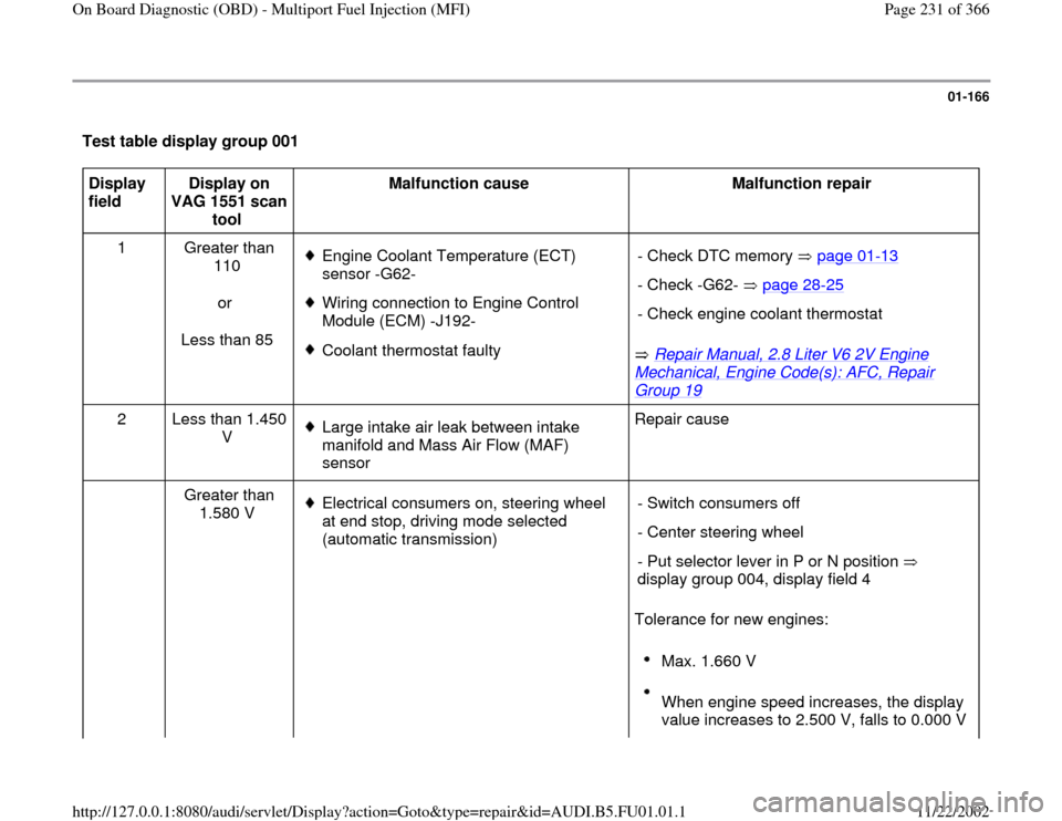
Test table display group 001 Display
field Display on
VAG 1551 scan
tool Malfunction cause
Malfunction repair
1 Greater than
110
or
Less than 85
Engine Coolant Temperature (ECT)
sensor -G62-
Wiring connection to Engine Control
Module (ECM) -J192-
Coolant thermostat faulty
Repair Manual, 2.8 Liter V6 2V Engine
Mechanical, Engine Code(s): AFC, Repair Group 19
- Check DTC memory page 01
-13
- Check -G62- page 28
-25
- Check engine coolant thermostat
2 Less than 1.450
V
Large intake air leak between intake
manifold and Mass Air Flow (MAF)
sensor Repair cause
Greater than
1.580 V Electrical consumers on, steering wheel
at end stop, driving mode selected
(automatic transmission)
Tolerance for new engines: - Switch consumers off
- Center steering wheel
- Put selector lever in P or N position
display group 004, display field 4
Max. 1.660 V
When engine speed increases, the display
value increases to 2.500 V, falls to 0.000 V
Pa
ge 231 of 366 On Board Dia
gnostic
(OBD
) - Multi
port Fuel In
jection
(MFI
)
11/22/2002 htt
p://127.0.0.1:8080/audi/servlet/Dis
play?action=Goto&t
yp
e=re
pair&id=AUDI.B5.FU01.01.1
Page 232 of 366
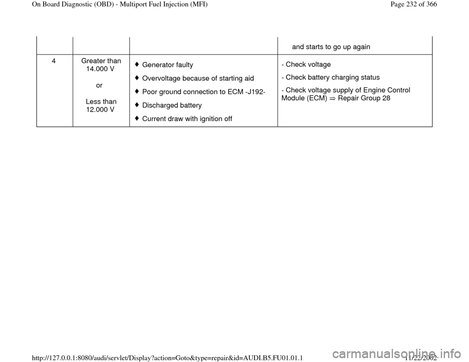
and starts to go up again
4 Greater than
14.000 V
or
Less than
12.000 V
Generator faulty
Overvoltage because of starting aid
Poor ground connection to ECM -J192-
Discharged battery
Current draw with ignition off - Check voltage
- Check battery charging status
- Check voltage supply of Engine Control
Module (ECM) Repair Group 28
Pa
ge 232 of 366 On Board Dia
gnostic
(OBD
) - Multi
port Fuel In
jection
(MFI
)
11/22/2002 htt
p://127.0.0.1:8080/audi/servlet/Dis
play?action=Goto&t
yp
e=re
pair&id=AUDI.B5.FU01.01.1
Page 235 of 366
01-169
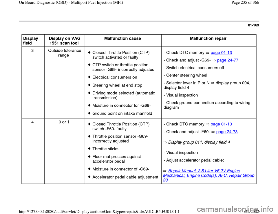
Display
field Display on VAG
1551 scan tool Malfunction cause
Malfunction repair
3 Outside tolerance
range
Closed Throttle Position (CTP)
switch activated or faulty CTP switch or throttle position
sensor -G69- incorrectly adjusted Electrical consumers onSteering wheel at end stopDriving mode selected (automatic
transmission) Moisture in connector for -G69-Ground point on intake manifold - Check DTC memory page 01
-13
- Check and adjust -G69- page 24
-77
- Switch electrical consumers off
- Center steering wheel
- Selector lever in P or N display group 004,
display field 4 - Visual inspection
- Check ground connection according to wiring
diagram
4 0 or 1
Closed Throttle Position (CTP)
switch -F60- faulty Throttle position sensor -G69-
incorrectly adjusted Throttle sticks Floor mat presses against
accelerator pedal Moisture in connector of -G69-Accelerator pedal cable adjustment Display group 011, display field 4
Repair Manual, 2.8 Liter V6 2V Engine
Mechanical, Engine Code(s): AFC, Repair Group 20
- Check DTC memory page 01
-13
- Check and adjust -F60- page 24
-73
- Visual inspection
- Adjust accelerator pedal cable:
Pa
ge 235 of 366 On Board Dia
gnostic
(OBD
) - Multi
port Fuel In
jection
(MFI
)
11/22/2002 htt
p://127.0.0.1:8080/audi/servlet/Dis
play?action=Goto&t
yp
e=re
pair&id=AUDI.B5.FU01.01.1
Page 237 of 366
01-170
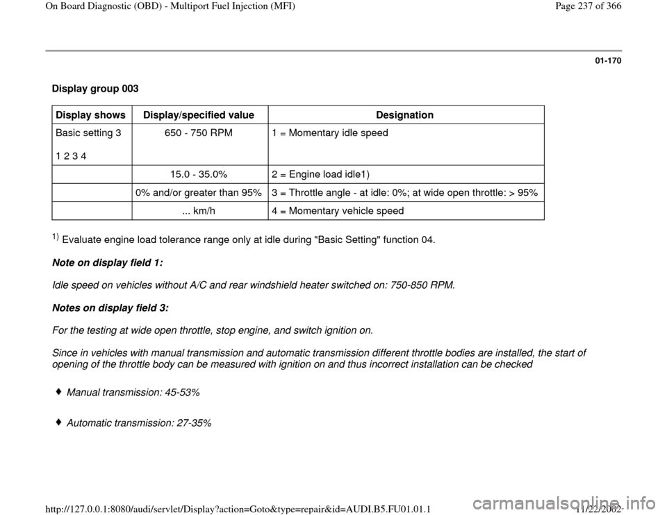
Display group 003 Display shows
Display/specified value
Designation
Basic setting 3
1 2 3 4 650 - 750 RPM 1 = Momentary idle speed
15.0 - 35.0% 2 = Engine load idle1)
0% and/or greater than 95% 3 = Throttle angle - at idle: 0%; at wide open throttle: > 95%
... km/h 4 = Momentary vehicle speed 1) Evaluate engine load tolerance range only at idle during "Basic Setting" function 04.
Note on display field 1:
Idle speed on vehicles without A/C and rear windshield heater switched on: 750-850 RPM.
Notes on display field 3:
For the testing at wide open throttle, stop engine, and switch ignition on.
Since in vehicles with manual transmission and automatic transmission different throttle bodies are installed, the start of
opening of the throttle body can be measured with ignition on and thus incorrect installation can be checked
Manual transmission: 45-53%
Automatic transmission: 27-35%
Pa
ge 237 of 366 On Board Dia
gnostic
(OBD
) - Multi
port Fuel In
jection
(MFI
)
11/22/2002 htt
p://127.0.0.1:8080/audi/servlet/Dis
play?action=Goto&t
yp
e=re
pair&id=AUDI.B5.FU01.01.1
Page 240 of 366
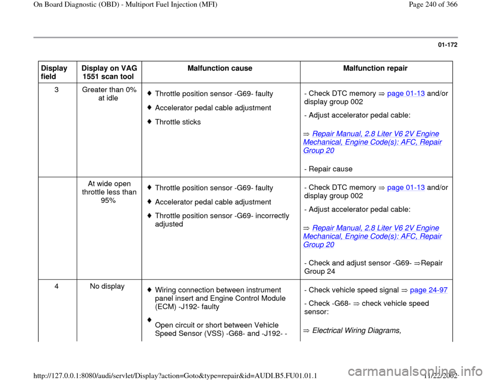
01-172
Display
field Display on VAG
1551 scan tool Malfunction cause
Malfunction repair
3 Greater than 0%
at idle
Throttle position sensor -G69- faultyAccelerator pedal cable adjustmentThrottle sticks
Repair Manual, 2.8 Liter V6 2V Engine
Mechanical, Engine Code(s): AFC, Repair Group 20
- Check DTC memory page 01
-13
and/or
display group 002
- Adjust accelerator pedal cable:- Repair cause
At wide open
throttle less than
95%
Throttle position sensor -G69- faultyAccelerator pedal cable adjustment Throttle position sensor -G69- incorrectly
adjusted
Repair Manual, 2.8 Liter V6 2V Engine
Mechanical, Engine Code(s): AFC, Repair Group 20
- Check DTC memory page 01
-13
and/or
display group 002
- Adjust accelerator pedal cable:- Check and adjust sensor -G69- Repair
Group 24
4 No display
Wiring connection between instrument
panel insert and Engine Control Module
(ECM) -J192- faulty Open circuit or short between Vehicle
Speed Sensor (VSS) -G68- and -J192- - Electrical Wiring Diagrams, - Check vehicle speed signal page 24
-97
- Check -G68- check vehicle speed
sensor:
Pa
ge 240 of 366 On Board Dia
gnostic
(OBD
) - Multi
port Fuel In
jection
(MFI
)
11/22/2002 htt
p://127.0.0.1:8080/audi/servlet/Dis
play?action=Goto&t
yp
e=re
pair&id=AUDI.B5.FU01.01.1
Page 247 of 366
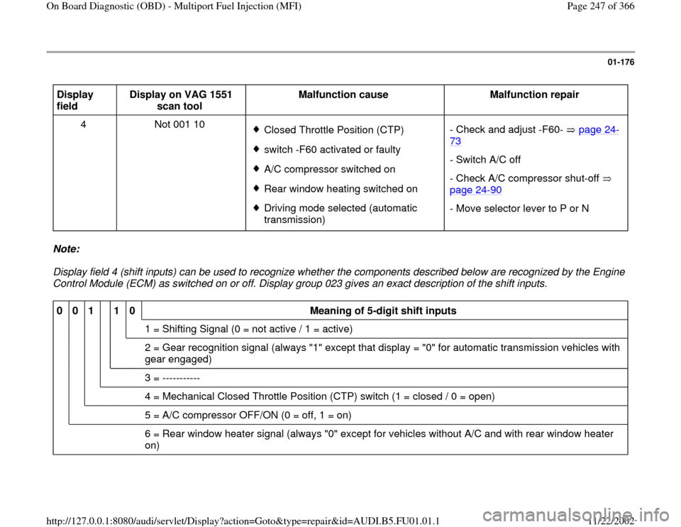
01-176
Display
field Display on VAG 1551
scan tool Malfunction cause
Malfunction repair
4 Not 001 10
Closed Throttle Position (CTP) switch -F60 activated or faulty A/C compressor switched on Rear window heating switched on Driving mode selected (automatic
transmission) - Check and adjust -F60- page 24
-
73
- Switch A/C off
- Check A/C compressor shut-off
page 24
-90
- Move selector lever to P or N
Note:
Display field 4 (shift inputs) can be used to recognize whether the components described below are recognized by the Engine
Control Module (ECM) as switched on or off. Display group 023 gives an exact description of the shift inputs. 0
0
1
1
0
Meaning of 5-digit shift inputs
1 = Shifting Signal (0 = not active / 1 = active)
2 = Gear recognition signal (always "1" except that display = "0" for automatic transmission vehicles with
gear engaged)
3 = -----------
4 = Mechanical Closed Throttle Position (CTP) switch (1 = closed / 0 = open)
5 = A/C compressor OFF/ON (0 = off, 1 = on)
6 = Rear window heater signal (always "0" except for vehicles without A/C and with rear window heater
on)
Pa
ge 247 of 366 On Board Dia
gnostic
(OBD
) - Multi
port Fuel In
jection
(MFI
)
11/22/2002 htt
p://127.0.0.1:8080/audi/servlet/Dis
play?action=Goto&t
yp
e=re
pair&id=AUDI.B5.FU01.01.1
Page 258 of 366
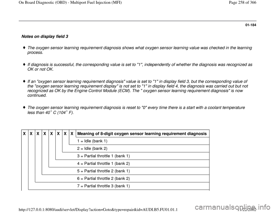
01-184
Notes on display field 3
The oxygen sensor learning requirement diagnosis shows what oxygen sensor learning value was checked in the learning
process.
If diagnosis is successful, the corresponding value is set to "1", independently of whether the diagnosis was recognized as
OK or not OK.
If an "oxygen sensor learning requirement diagnosis" value is set to "1" in display field 3, but the corresponding value of
the "oxygen sensor learning requirement display" is not set to "1" in display field 4, the diagnosis was carried out but not
recognized as OK by the Engine Control Module (ECM). The " oxygen sensor learning requirement diagnosis" is now
continued.
The oxygen sensor learning requirement diagnosis is reset to "0" every time there is a start with a coolant temperature
less than 40 C (104 F).
X
X
X
X
X
X
X
X
Meaning of 8-digit oxygen sensor learning requirement diagnosis
1 = Idle (bank 1)
2 = Idle (bank 2)
3 = Partial throttle 1 (bank 1)
4 = Partial throttle 1 (bank 2)
5 = Partial throttle 2 (bank 1)
6 = Partial throttle 2 (bank 2)
7 = Partial throttle 3 (bank 1)
Pa
ge 258 of 366 On Board Dia
gnostic
(OBD
) - Multi
port Fuel In
jection
(MFI
)
11/22/2002 htt
p://127.0.0.1:8080/audi/servlet/Dis
play?action=Goto&t
yp
e=re
pair&id=AUDI.B5.FU01.01.1
Page 266 of 366

01-190
Test table display group 010 Display
fields Display on VAG 1551 scan tool
Malfunction cause
Malfunction repair
1/2 Difference between display value
1 (bank 1) and display value 2
(bank 2) greater than 8%
Spark plug faultyIntake air leak on one side Fuel injectors faulty - Repair cause
- Check DTC memory page 01
-13
and/or check fuel injectors page 24-
29
Heated Oxygen Sensor
(HO2S) faulty (dirty) - Check DTC memory page 01
-13
and/or display fields 3 and 4
Mechanical engine basic
setting (valve/camshaft
timing) not OK
Repair Manual, 2.8 Liter V6 2V
Engine Mechanical, Engine Code(s): AFC, Repair Group 13
- Check valve/camshaft timing
Pa
ge 266 of 366 On Board Dia
gnostic
(OBD
) - Multi
port Fuel In
jection
(MFI
)
11/22/2002 htt
p://127.0.0.1:8080/audi/servlet/Dis
play?action=Goto&t
yp
e=re
pair&id=AUDI.B5.FU01.01.1
Page 267 of 366
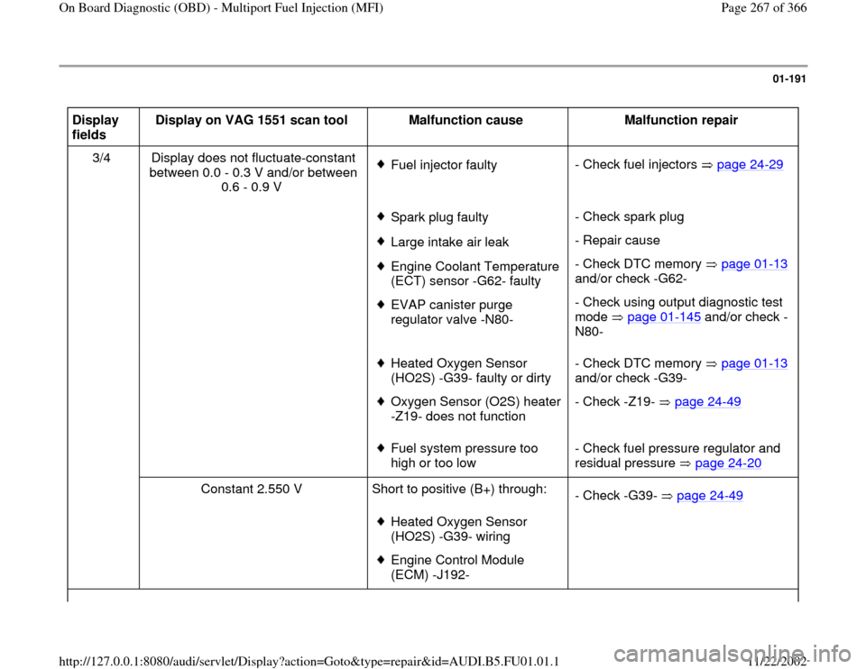
01-191
Display
fields Display on VAG 1551 scan tool
Malfunction cause
Malfunction repair
3/4 Display does not fluctuate-constant
between 0.0 - 0.3 V and/or between
0.6 - 0.9 V
Fuel injector faulty- Check fuel injectors page 24
-29
Spark plug faultyLarge intake air leak Engine Coolant Temperature
(ECT) sensor -G62- faulty EVAP canister purge
regulator valve -N80- - Check spark plug
- Repair cause
- Check DTC memory page 01
-13
and/or check -G62-
- Check using output diagnostic test
mode page 01
-145
and/or check -
N80-
Heated Oxygen Sensor
(HO2S) -G39- faulty or dirty Oxygen Sensor (O2S) heater
-Z19- does not function - Check DTC memory page 01
-13
and/or check -G39-
- Check -Z19- page 24
-49
Fuel system pressure too
high or too low - Check fuel pressure regulator and
residual pressure page 24
-20
Constant 2.550 V Short to positive (B+) through:
Heated Oxygen Sensor
(HO2S) -G39- wiring Engine Control Module
(ECM) -J192- - Check -G39- page 24
-49Pa
ge 267 of 366 On Board Dia
gnostic
(OBD
) - Multi
port Fuel In
jection
(MFI
)
11/22/2002 htt
p://127.0.0.1:8080/audi/servlet/Dis
play?action=Goto&t
yp
e=re
pair&id=AUDI.B5.FU01.01.1
Page 269 of 366
01-192
Display
fields Display on VAG 1551 scan tool
Malfunction cause
Malfunction repair
3/4
Constant value between 0.350 -
0.450 V Open circuit in:
Heated Oxygen Sensor (HO2S) -G39-
wiring Engine Control Module (ECM) -J192-- Check -G39- page
24
-49
Constant 0.000 V Short to ground in:
Heated Oxygen Sensor (HO2S) -G39-
wiring Engine Control Module (ECM) -J192-- Check -G39- page
24
-49
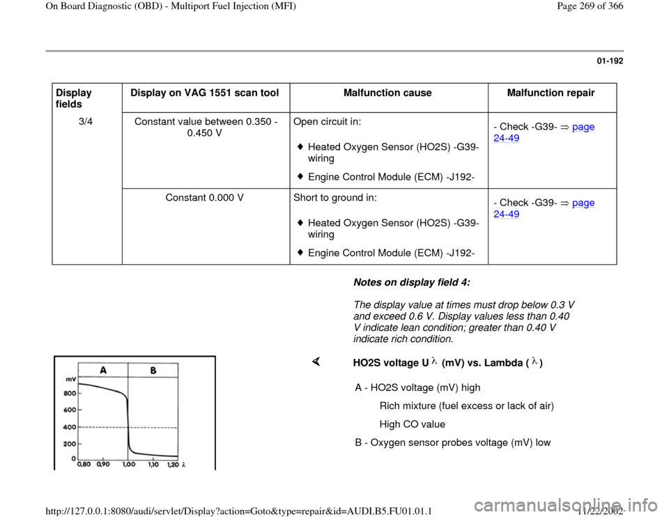
Notes on display field 4:
The display value at times must drop below 0.3 V
and exceed 0.6 V. Display values less than 0.40
V indicate lean condition; greater than 0.40 V
indicate rich condition.
HO2S voltage U (mV) vs. Lambda ( ) A - HO2S voltage (mV) high
Rich mixture (fuel excess or lack of air)
High CO value
B - Oxygen sensor probes voltage (mV) low
Pa
ge 269 of 366 On Board Dia
gnostic
(OBD
) - Multi
port Fuel In
jection
(MFI
)
11/22/2002 htt
p://127.0.0.1:8080/audi/servlet/Dis
play?action=Goto&t
yp
e=re
pair&id=AUDI.B5.FU01.01.1