display AUDI A4 1996 B5 / 1.G AFC Engine On Board Diagnostic Multiport Fuel Injection Workshop Manual
[x] Cancel search | Manufacturer: AUDI, Model Year: 1996, Model line: A4, Model: AUDI A4 1996 B5 / 1.GPages: 366, PDF Size: 1.21 MB
Page 3 of 366
01-2
On Board Diagnostic (OBD) II technical data
Memory
Permanent memory (If the engine control module is disconnected from the permanent battery positive voltage (B+) supply,
the Diagnostic Trouble Code (DTC) memory and "Readiness Code" will be erased.)
Data output
Rapid data transfer
Additional malfunction display by Malfunction Indicator Light (MIL) lighting up
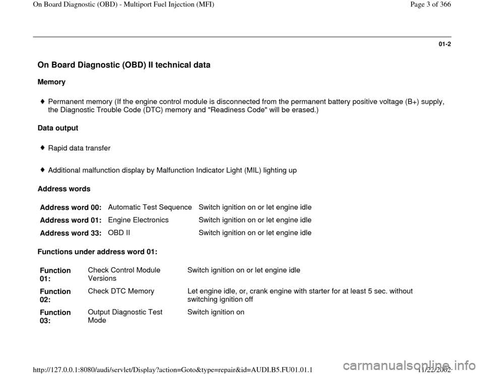
Address words
Address word 00: Automatic Test Sequence Switch ignition on or let engine idle
Address word 01: Engine Electronics Switch ignition on or let engine idle
Address word 33: OBD II Switch ignition on or let engine idle
Functions under address word 01:
Function
01: Check Control Module
Versions Switch ignition on or let engine idle
Function
02: Check DTC Memory Let engine idle, or, crank engine with starter for at least 5 sec. without
switching ignition off
Function
03: Output Diagnostic Test
Mode Switch ignition on
Pa
ge 3 of 366 On Board Dia
gnostic
(OBD
) - Multi
port Fuel In
jection
(MFI
)
11/22/2002 htt
p://127.0.0.1:8080/audi/servlet/Dis
play?action=Goto&t
yp
e=re
pair&id=AUDI.B5.FU01.01.1
Page 5 of 366
01-3
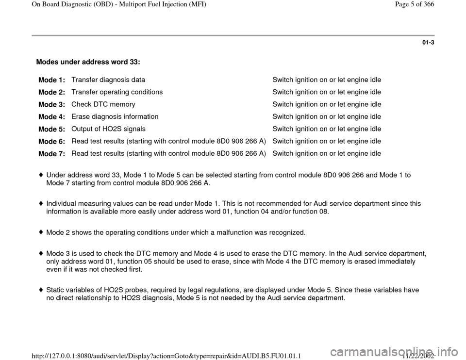
Modes under address word 33:
Mode 1: Transfer diagnosis data Switch ignition on or let engine idle
Mode 2: Transfer operating conditions Switch ignition on or let engine idle
Mode 3: Check DTC memory Switch ignition on or let engine idle
Mode 4: Erase diagnosis information Switch ignition on or let engine idle
Mode 5: Output of HO2S signals Switch ignition on or let engine idle
Mode 6: Read test results (starting with control module 8D0 906 266 A) Switch ignition on or let engine idle
Mode 7: Read test results (starting with control module 8D0 906 266 A) Switch ignition on or let engine idle
Under address word 33, Mode 1 to Mode 5 can be selected starting from control module 8D0 906 266 and Mode 1 to
Mode 7 starting from control module 8D0 906 266 A.
Individual measuring values can be read under Mode 1. This is not recommended for Audi service department since this
information is available more easily under address word 01, function 04 and/or function 08.
Mode 2 shows the operating conditions under which a malfunction was recognized.
Mode 3 is used to check the DTC memory and Mode 4 is used to erase the DTC memory. In the Audi service department,
only address word 01, function 05 should be used to erase, since with Mode 4 the DTC memory is erased immediately
even if it was not checked first.
Static variables of HO2S probes, required by legal regulations, are displayed under Mode 5. Since these variables have
no direct relationship to HO2S diagnosis, Mode 5 is not needed by the Audi service department.
Pa
ge 5 of 366 On Board Dia
gnostic
(OBD
) - Multi
port Fuel In
jection
(MFI
)
11/22/2002 htt
p://127.0.0.1:8080/audi/servlet/Dis
play?action=Goto&t
yp
e=re
pair&id=AUDI.B5.FU01.01.1
Page 8 of 366
01-5
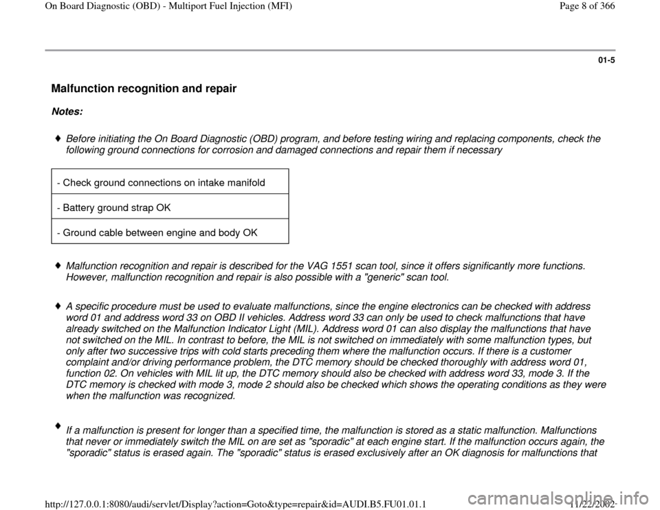
Malfunction recognition and repair
Notes:
Before initiating the On Board Diagnostic (OBD) program, and before testing wiring and replacing components, check the
following ground connections for corrosion and damaged connections and repair them if necessary
- Check ground connections on intake manifold
- Battery ground strap OK
- Ground cable between engine and body OK Malfunction recognition and repair is described for the VAG 1551 scan tool, since it offers significantly more functions.
However, malfunction recognition and repair is also possible with a "generic" scan tool.
A specific procedure must be used to evaluate malfunctions, since the engine electronics can be checked with address
word 01 and address word 33 on OBD II vehicles. Address word 33 can only be used to check malfunctions that have
already switched on the Malfunction Indicator Light (MIL). Address word 01 can also display the malfunctions that have
not switched on the MIL. In contrast to before, the MIL is not switched on immediately with some malfunction types, but
only after two successive trips with cold starts preceding them where the malfunction occurs. If there is a customer
complaint and/or driving performance problem, the DTC memory should be checked thoroughly with address word 01,
function 02. On vehicles with MIL lit up, the DTC memory should also be checked with address word 33, mode 3. If the
DTC memory is checked with mode 3, mode 2 should also be checked which shows the operating conditions as they were
when the malfunction was recognized.
If a malfunction is present for longer than a specified time, the malfunction is stored as a static malfunction. Malfunctions
that never or immediately switch the MIL on are set as "sporadic" at each engine start. If the malfunction occurs again, the
"sporadic" status is erased again. The "sporadic" status is erased exclusively after an OK diagnosis for malfunctions that
Pa
ge 8 of 366 On Board Dia
gnostic
(OBD
) - Multi
port Fuel In
jection
(MFI
)
11/22/2002 htt
p://127.0.0.1:8080/audi/servlet/Dis
play?action=Goto&t
yp
e=re
pair&id=AUDI.B5.FU01.01.1
Page 12 of 366
01-8
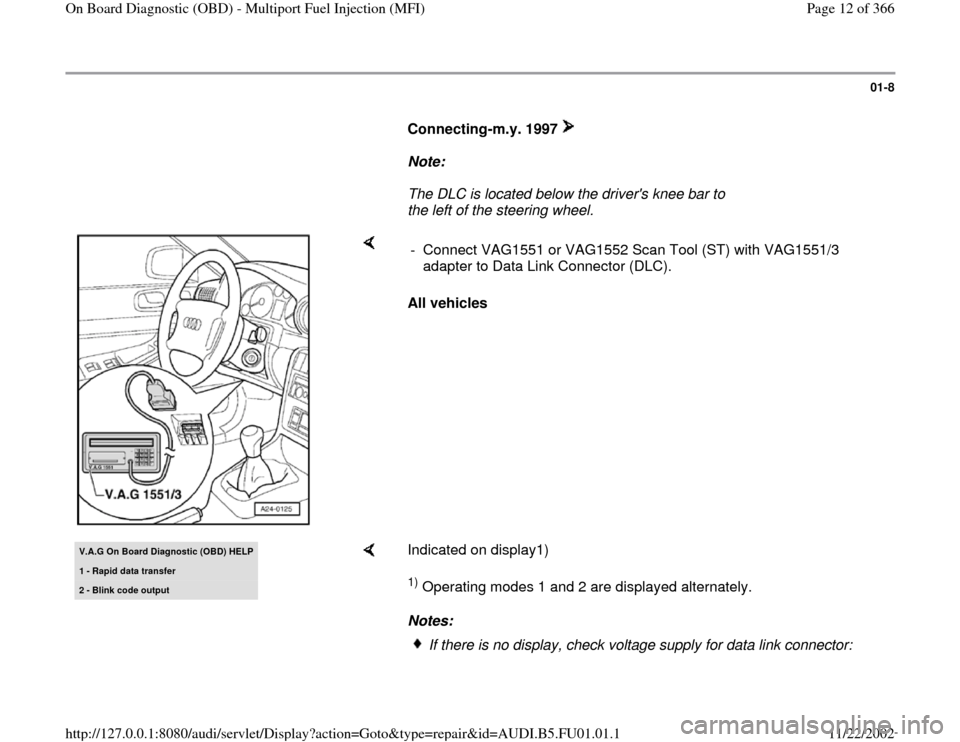
Connecting-m.y. 1997
Note:
The DLC is located below the driver's knee bar to
the left of the steering wheel.
All vehicles - Connect VAG1551 or VAG1552 Scan Tool (ST) with VAG1551/3
adapter to Data Link Connector (DLC).
V.A.G On Board Dia
gnostic
(OBD
) HELP
1 - Rapid data transfer2 - Blink code output
Indicated on display1) 1) Operating modes 1 and 2 are displayed alternately.
Notes: If there is no display, check voltage supply for data link connector:
Pa
ge 12 of 366 On Board Dia
gnostic
(OBD
) - Multi
port Fuel In
jection
(MFI
)
11/22/2002 htt
p://127.0.0.1:8080/audi/servlet/Dis
play?action=Goto&t
yp
e=re
pair&id=AUDI.B5.FU01.01.1
Page 14 of 366
01-9
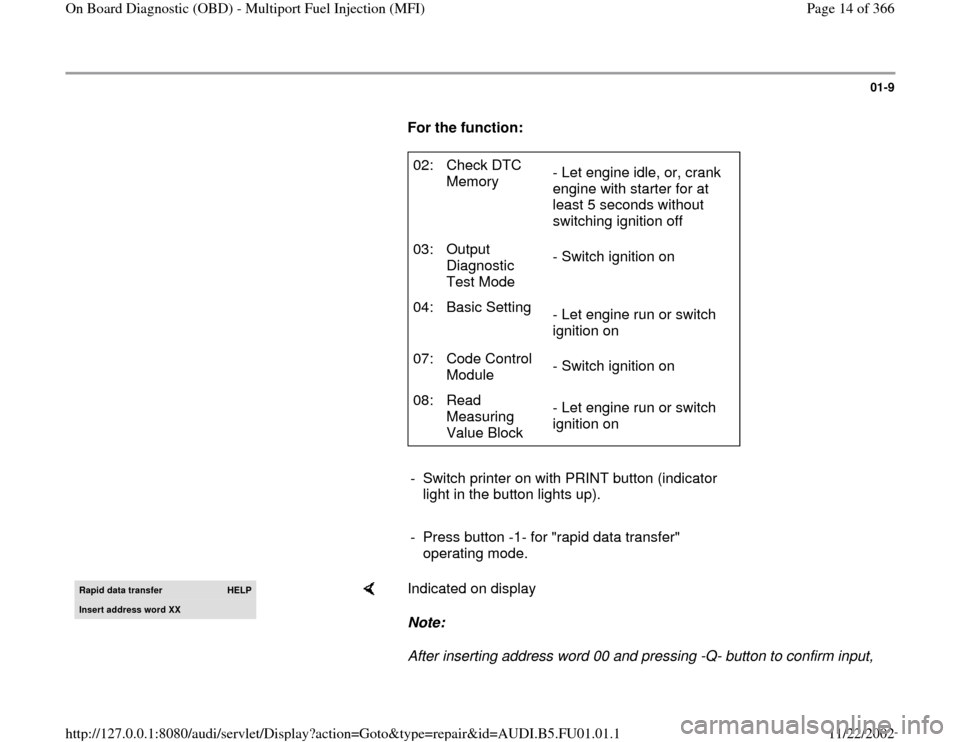
For the function:
02: Check DTC
Memory - Let engine idle, or, crank
engine with starter for at
least 5 seconds without
switching ignition off
03: Output
Diagnostic
Test Mode - Switch ignition on
04: Basic Setting
- Let engine run or switch
ignition on
07: Code Control
Module - Switch ignition on
08: Read
Measuring
Value Block - Let engine run or switch
ignition on
- Switch printer on with PRINT button (indicator
light in the button lights up).
- Press button -1- for "rapid data transfer"
operating mode.
Rapid data transfer
HELP
Insert address word XX
Indicated on display
Note:
After inserting address word 00 and pressing -Q- button to confirm input,
Pa
ge 14 of 366 On Board Dia
gnostic
(OBD
) - Multi
port Fuel In
jection
(MFI
)
11/22/2002 htt
p://127.0.0.1:8080/audi/servlet/Dis
play?action=Goto&t
yp
e=re
pair&id=AUDI.B5.FU01.01.1
Page 16 of 366
01-10
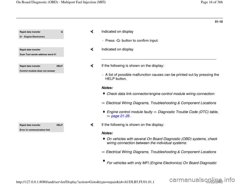
Rapid data transfer
Q
01 - Engine Electronics
Indicated on display
- Press -Q- button to confirm input.
Rapid data transfer Scan Tool sends address word 01
Indicated on display
_________________________________________________________
Rapid data transfer
HELP
Control module does not answer
If the following is shown on the display:
Notes:
Electrical Wiring Diagrams, Troubleshooting & Component Locations - A list of possible malfunction causes can be printed out by pressing the
HELP button.
Check data link connector/engine control module wiring connection:Engine control module faulty Diagnostic Trouble Code (DTC) table,
page 01
-26
.
Rapid data transfer
HELP
Error in communication link
If the following is shown on the display:
Notes:
Electrical Wiring Diagrams, Troubleshooting & Component Locations
On vehicles with several On Board Diagnostic (OBD) systems, check
wiring connection between the individual systems: For vehicles with only MFI (Engine Electronics) On Board Diagnostic
Pa
ge 16 of 366 On Board Dia
gnostic
(OBD
) - Multi
port Fuel In
jection
(MFI
)
11/22/2002 htt
p://127.0.0.1:8080/audi/servlet/Dis
play?action=Goto&t
yp
e=re
pair&id=AUDI.B5.FU01.01.1
Page 18 of 366
01-11
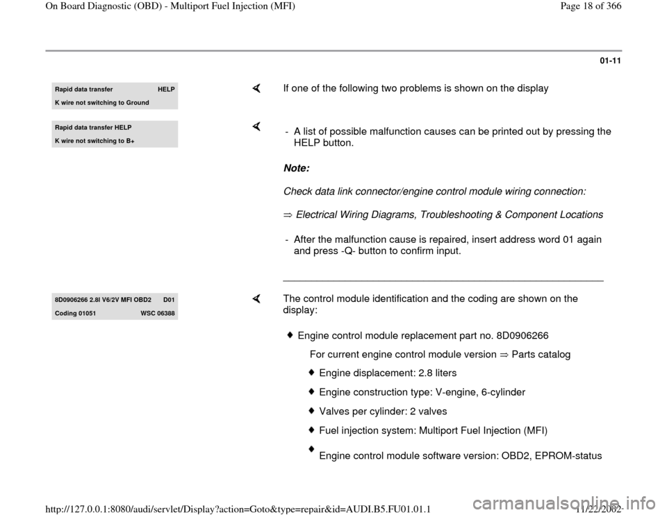
Rapid data transfer
HELP
K wire not switching to Ground
If one of the following two problems is shown on the display
Rapid data transfer HELPK wire not switching to B+
Note:
Check data link connector/engine control module wiring connection:
Electrical Wiring Diagrams, Troubleshooting & Component Locations
_________________________________________________________ - A list of possible malfunction causes can be printed out by pressing the
HELP button. - After the malfunction cause is repaired, insert address word 01 again
and press -Q- button to confirm input.
8D0906266 2.8l V6/2V MFI OBD2
D01
Codin
g 01051
WSC 06388
The control module identification and the coding are shown on the
display:
Engine control module replacement part no. 8D0906266
For current engine control module version Parts catalog
Engine displacement: 2.8 liters Engine construction type: V-engine, 6-cylinderValves per cylinder: 2 valvesFuel injection system: Multiport Fuel Injection (MFI)Engine control module software version: OBD2, EPROM-status
Pa
ge 18 of 366 On Board Dia
gnostic
(OBD
) - Multi
port Fuel In
jection
(MFI
)
11/22/2002 htt
p://127.0.0.1:8080/audi/servlet/Dis
play?action=Goto&t
yp
e=re
pair&id=AUDI.B5.FU01.01.1
Page 20 of 366
01-12
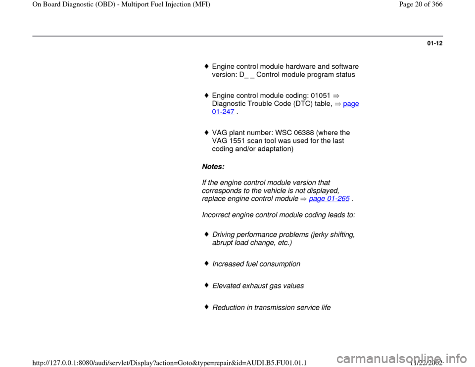
Engine control module hardware and software
version: D_ _ Control module program status
Engine control module coding: 01051
Diagnostic Trouble Code (DTC) table, page 01
-247
.
VAG plant number: WSC 06388 (where the
VAG 1551 scan tool was used for the last
coding and/or adaptation)
Notes:
If the engine control module version that
corresponds to the vehicle is not displayed,
replace engine control module page 01
-265
.
Incorrect engine control module coding leads to:
Driving performance problems (jerky shifting,
abrupt load change, etc.)
Increased fuel consumption
Elevated exhaust gas values
Reduction in transmission service life
Pa
ge 20 of 366 On Board Dia
gnostic
(OBD
) - Multi
port Fuel In
jection
(MFI
)
11/22/2002 htt
p://127.0.0.1:8080/audi/servlet/Dis
play?action=Goto&t
yp
e=re
pair&id=AUDI.B5.FU01.01.1
Page 21 of 366
Malfunctions not present are stored in DTC
memory
Functions are not carried out (oxygen sensor
control, actuation of EVAP canister system,
etc.)
-
Press button.
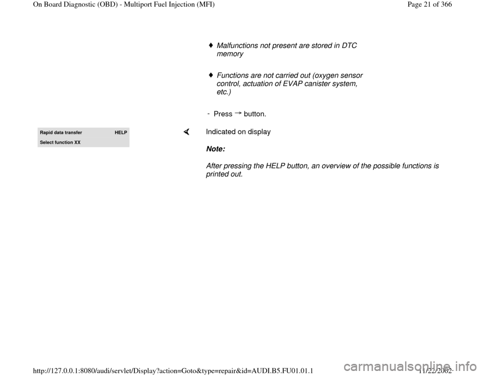
Rapid data transfer
HELP
Select function XX
Indicated on display
Note:
After pressing the HELP button, an overview of the possible functions is
printed out.
Pa
ge 21 of 366 On Board Dia
gnostic
(OBD
) - Multi
port Fuel In
jection
(MFI
)
11/22/2002 htt
p://127.0.0.1:8080/audi/servlet/Dis
play?action=Goto&t
yp
e=re
pair&id=AUDI.B5.FU01.01.1
Page 22 of 366
01-13
DTC memory, checking and erasing
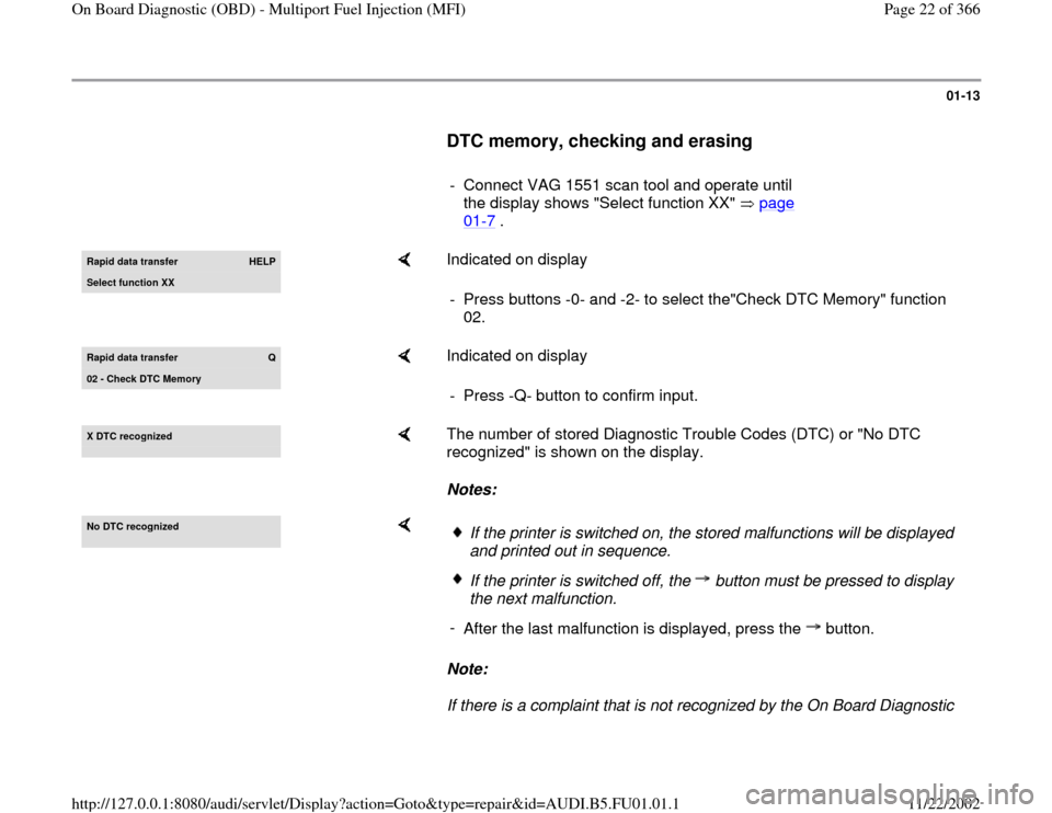
- Connect VAG 1551 scan tool and operate until
the display shows "Select function XX" page
01
-7 .
Rapid data transfer
HELP
Select function XX
Indicated on display
- Press buttons -0- and -2- to select the"Check DTC Memory" function
02.
Rapid data transfer
Q
02 - Check DTC Memor
y
Indicated on display
- Press -Q- button to confirm input.
X DTC reco
gnized
The number of stored Diagnostic Trouble Codes (DTC) or "No DTC
recognized" is shown on the display.
Notes:
No DTC reco
gnized
Note:
If there is a complaint that is not recognized by the On Board Diagnostic
If the printer is switched on, the stored malfunctions will be displayed
and printed out in sequence. If the printer is switched off, the button must be pressed to display
the next malfunction.
-
After the last malfunction is displayed, press the button.
Pa
ge 22 of 366 On Board Dia
gnostic
(OBD
) - Multi
port Fuel In
jection
(MFI
)
11/22/2002 htt
p://127.0.0.1:8080/audi/servlet/Dis
play?action=Goto&t
yp
e=re
pair&id=AUDI.B5.FU01.01.1