diagram AUDI A4 1996 B5 / 1.G AHA Engine Multiport Fuel Injection And Ignition System Workshop Manual
[x] Cancel search | Manufacturer: AUDI, Model Year: 1996, Model line: A4, Model: AUDI A4 1996 B5 / 1.GPages: 166, PDF Size: 0.91 MB
Page 26 of 166
24-21
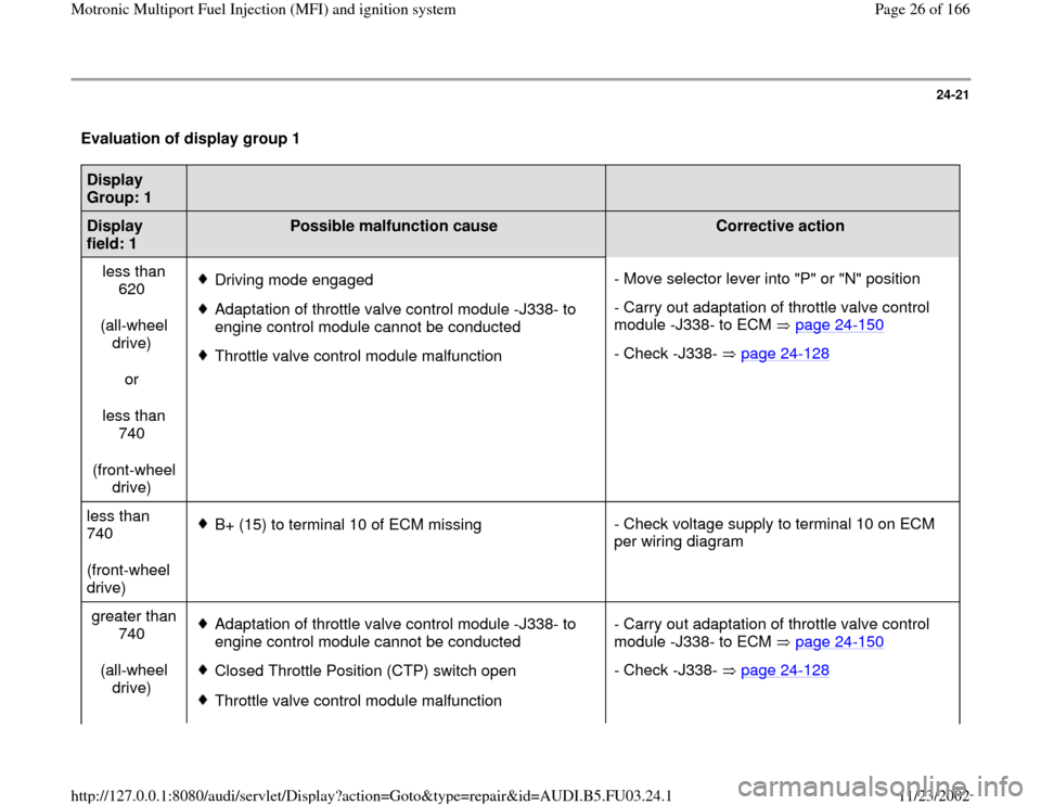
Evaluation of display group 1 Display
Group: 1
Display
field: 1
Possible malfunction cause
Corrective action
less than
620
(all-wheel
drive)
or
less than
740
(front-wheel
drive)
Driving mode engaged
Adaptation of throttle valve control module -J338- to
engine control module cannot be conducted
Throttle valve control module malfunction- Move selector lever into "P" or "N" position
- Carry out adaptation of throttle valve control
module -J338- to ECM page 24
-150
- Check -J338- page 24
-128
less than
740
(front-wheel
drive)
B+ (15) to terminal 10 of ECM missing- Check voltage supply to terminal 10 on ECM
per wiring diagram
greater than
740
(all-wheel
drive) Adaptation of throttle valve control module -J338- to
engine control module cannot be conducted
Closed Throttle Position (CTP) switch open
Throttle valve control module malfunction- Carry out adaptation of throttle valve control
module -J338- to ECM page 24
-150
- Check -J338- page 24
-128
Pa
ge 26 of 166 Motronic Multi
port Fuel In
jection
(MFI
) and i
gnition s
ystem
11/23/2002 htt
p://127.0.0.1:8080/audi/servlet/Dis
play?action=Goto&t
yp
e=re
pair&id=AUDI.B5.FU03.24.1
Page 29 of 166
Wiring diagram
Test conditions
Engine Coolant Temperature (ECT) at least
80 C (176 F)
Pa
ge 29 of 166 Motronic Multi
port Fuel In
jection
(MFI
) and i
gnition s
ystem
11/23/2002 htt
p://127.0.0.1:8080/audi/servlet/Dis
play?action=Goto&t
yp
e=re
pair&id=AUDI.B5.FU03.24.1
Page 44 of 166
24-34
Oxygen Sensor (O2S) heater before
TWC, checking
Notes:
Connector for Oxygen Sensor (O2S) heater -
Z19- (bank 1, sensor 1): 4-pin, black.
Connector for Oxygen Sensor (O2S) 2 heater -
Z28- (Bank 2, sensor 1): 4-pin, black.
Component locations page 24
-1 .
Required special tools and test equipment
VAG1551 or VAG1552 Scan Tool (ST) with
VAG1551/3 adapter cable
VAG1598/22 test box
Multimeter US1119 (Fluke 83 or equivalent)
VW1594 connector test kit
Wiring diagram
Test requirements
Pa
ge 44 of 166 Motronic Multi
port Fuel In
jection
(MFI
) and i
gnition s
ystem
11/23/2002 htt
p://127.0.0.1:8080/audi/servlet/Dis
play?action=Goto&t
yp
e=re
pair&id=AUDI.B5.FU03.24.1
Page 51 of 166
24-39
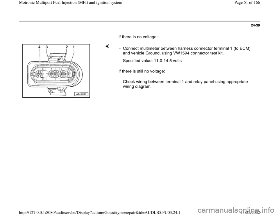
If there is no voltage:
If there is still no voltage: - Connect multimeter between harness connector terminal 1 (to ECM)
and vehicle Ground, using VW1594 connector test kit.
Specified value: 11.0-14.5 volts
- Check wiring between terminal 1 and relay panel using appropriate
wiring diagram.
Pa
ge 51 of 166 Motronic Multi
port Fuel In
jection
(MFI
) and i
gnition s
ystem
11/23/2002 htt
p://127.0.0.1:8080/audi/servlet/Dis
play?action=Goto&t
yp
e=re
pair&id=AUDI.B5.FU03.24.1
Page 55 of 166
Wiring diagram
Test requirements
Engine Coolant Temperature (ECT) at least
80 C (176 F)
Pa
ge 55 of 166 Motronic Multi
port Fuel In
jection
(MFI
) and i
gnition s
ystem
11/23/2002 htt
p://127.0.0.1:8080/audi/servlet/Dis
play?action=Goto&t
yp
e=re
pair&id=AUDI.B5.FU03.24.1
Page 65 of 166
24-52
Oxygen Sensor (O2S) heater behind
TWC, checking
Notes:
Connector for Oxygen Sensor (O2S) heater
(behind TWC) -Z29- (bank 1, sensor 2): 4-pin,
green
Connector for Oxygen Sensor (O2S) 2 (behind
TWC) -Z30- (bank 2, sensor 2): 4-pin, brown
Component locations page 24
-1
Required special tools and test equipment
VAG1551 or VAG1552 Scan Tool (ST) with
VAG1551/3 adapter cable
VAG1598/22 test box
Multimeter US1119 (Fluke 83 or equivalent)
VW1594 connector test kit
Wiring diagram
Pa
ge 65 of 166 Motronic Multi
port Fuel In
jection
(MFI
) and i
gnition s
ystem
11/23/2002 htt
p://127.0.0.1:8080/audi/servlet/Dis
play?action=Goto&t
yp
e=re
pair&id=AUDI.B5.FU03.24.1
Page 72 of 166
24-57
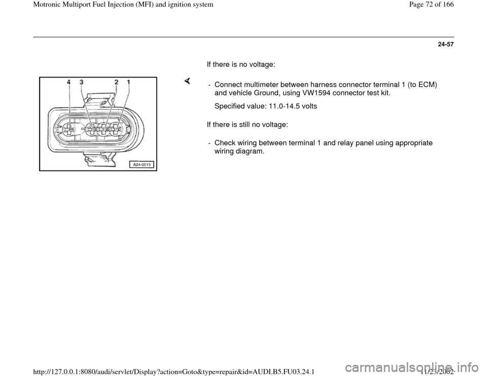
If there is no voltage:
If there is still no voltage: - Connect multimeter between harness connector terminal 1 (to ECM)
and vehicle Ground, using VW1594 connector test kit.
Specified value: 11.0-14.5 volts
- Check wiring between terminal 1 and relay panel using appropriate
wiring diagram.
Pa
ge 72 of 166 Motronic Multi
port Fuel In
jection
(MFI
) and i
gnition s
ystem
11/23/2002 htt
p://127.0.0.1:8080/audi/servlet/Dis
play?action=Goto&t
yp
e=re
pair&id=AUDI.B5.FU03.24.1
Page 89 of 166
24-68
Mass Air Flow (MAF) sensor, checking
Required special tools and test equipment
VAG1551 or VAG1552 Scan Tool (ST) with
VAG1551/3 adapter cable
VAG1598/22 test box
Multimeter US1119 (Fluke 83 or equivalent)
VW1594 connector test kit
Wiring diagram
Test requirements
All electrical consumers switched off (coolant
fan must not run during test).
A/C must be switched off
Fuse for MAF sensor OK
Pa
ge 89 of 166 Motronic Multi
port Fuel In
jection
(MFI
) and i
gnition s
ystem
11/23/2002 htt
p://127.0.0.1:8080/audi/servlet/Dis
play?action=Goto&t
yp
e=re
pair&id=AUDI.B5.FU03.24.1
Page 95 of 166
24-73
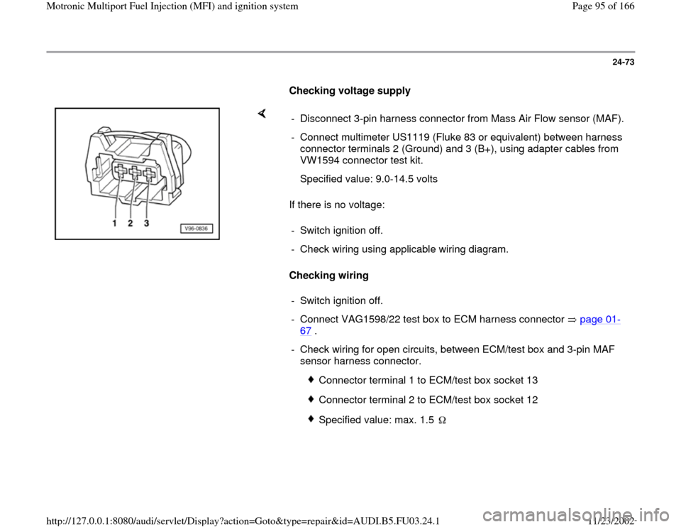
Checking voltage supply
If there is no voltage:
Checking wiring - Disconnect 3-pin harness connector from Mass Air Flow sensor (MAF).
- Connect multimeter US1119 (Fluke 83 or equivalent) between harness
connector terminals 2 (Ground) and 3 (B+), using adapter cables from
VW1594 connector test kit.
Specified value: 9.0-14.5 volts
- Switch ignition off.
- Check wiring using applicable wiring diagram.
- Switch ignition off.
- Connect VAG1598/22 test box to ECM harness connector page 01
-
67
.
- Check wiring for open circuits, between ECM/test box and 3-pin MAF
sensor harness connector.
Connector terminal 1 to ECM/test box socket 13
Connector terminal 2 to ECM/test box socket 12
Specified value: max. 1.5
Pa
ge 95 of 166 Motronic Multi
port Fuel In
jection
(MFI
) and i
gnition s
ystem
11/23/2002 htt
p://127.0.0.1:8080/audi/servlet/Dis
play?action=Goto&t
yp
e=re
pair&id=AUDI.B5.FU03.24.1
Page 96 of 166
24-74
- Check wiring for short circuits between terminals
of 3-pin connector, and between connector and
ECM/test box.
Connector terminal 1 to ECM/test box
socket 12
Specified value:
- Switch multimeter to 20 VDC measuring
range.
- Check wiring at 3-pin connector for short circuit
to B+ (battery positive voltage), according to
applicable wiring diagram.
Connector terminal 1 to vehicle Ground
Connector terminal 2 to vehicle Ground
Specified value: 0 volts
If wiring is OK:
- Replace Mass Air Flow sensor (MAF) -G70-.
-
Check readiness code page 01
-70
. If
Pa
ge 96 of 166 Motronic Multi
port Fuel In
jection
(MFI
) and i
gnition s
ystem
11/23/2002 htt
p://127.0.0.1:8080/audi/servlet/Dis
play?action=Goto&t
yp
e=re
pair&id=AUDI.B5.FU03.24.1