ignition AUDI A4 1996 B5 / 1.G APB Engine Motronic Multiport Fuel Injection System Servising User Guide
[x] Cancel search | Manufacturer: AUDI, Model Year: 1996, Model line: A4, Model: AUDI A4 1996 B5 / 1.GPages: 90, PDF Size: 0.84 MB
Page 48 of 90

24-41
- Switch ignition on. The diode test lamp should
light up.
- If diode test lamp does not light up, test for open
circuits in wiring between contact 1 and fuse for
injectors. If necessary, rectify open circuit.
Electrical Wiring Diagrams, Troubleshooting &
Component Locations
- If diode test lamp lights up, test activation of
injectors.
C - Testing activation of injectors
- Remove plug connector from the injector which
is to be tested.
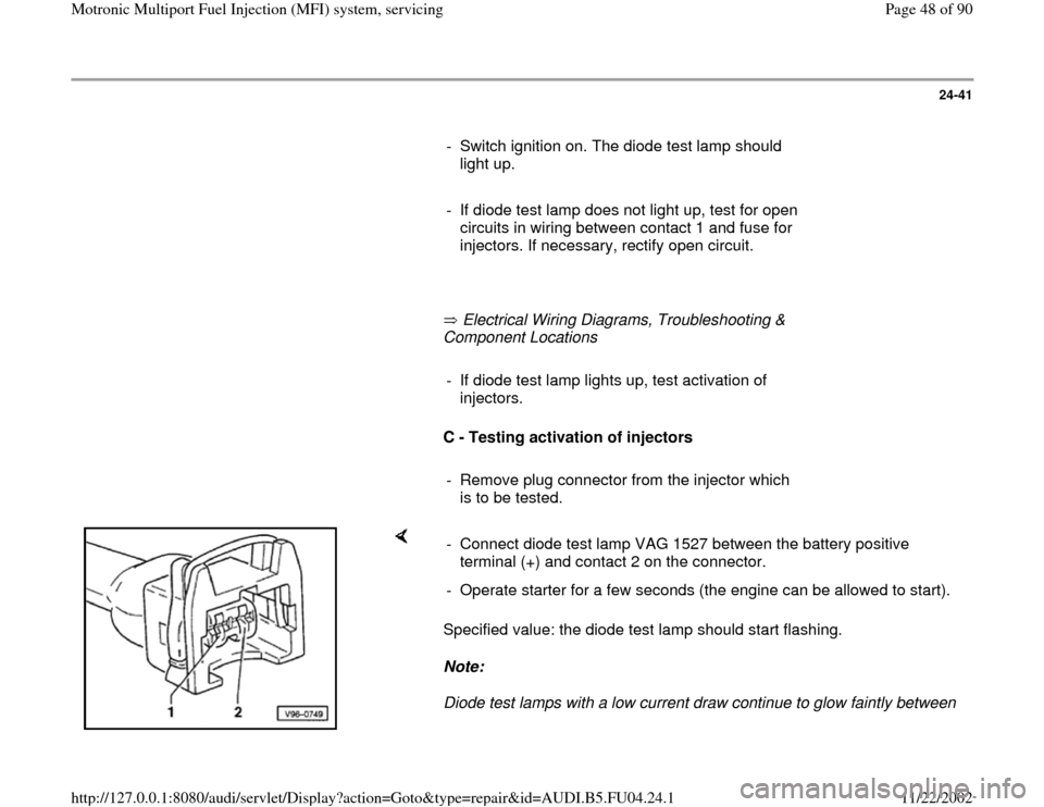
Specified value: the diode test lamp should start flashing.
Note:
Diode test lamps with a low current draw continue to glow faintly between - Connect diode test lamp VAG 1527 between the battery positive
terminal (+) and contact 2 on the connector.
- Operate starter for a few seconds (the engine can be allowed to start).
Pa
ge 48 of 90 Motronic Multi
port Fuel In
jection
(MFI
) system, servicin
g
11/22/2002 htt
p://127.0.0.1:8080/audi/servlet/Dis
play?action=Goto&t
yp
e=re
pair&id=AUDI.B5.FU04.24.1
Page 60 of 90

24-50
- Activate remote control VAG1348/3 A for 30
seconds.
- When all three fuel injectors from the first bank
of cylinders have been activated, place the three
measuring glasses on a level surface.
Specified value for each fuel injector: 135 ... 165
ml
- If measured value for one or more of fuel
injectors is outside tolerance range, switch off
fuel pump (switch ignition off) and replace faulty
fuel injector Page 24
-53
, also observe notes
on Page 24
-53
.
Pa
ge 60 of 90 Motronic Multi
port Fuel In
jection
(MFI
) system, servicin
g
11/22/2002 htt
p://127.0.0.1:8080/audi/servlet/Dis
play?action=Goto&t
yp
e=re
pair&id=AUDI.B5.FU04.24.1
Page 66 of 90

24-56
B - Checking voltage supply and activation of
fuel pump relay
Note:
Activation of the fuel pump relay can also be
tested using the final control diagnosis Page
01
-75
.
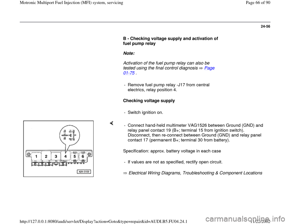
- Remove fuel pump relay -J17 from central
electrics, relay position 4.
Checking voltage supply
- Switch ignition on.
Specification: approx. battery voltage in each case
Electrical Wiring Diagrams, Troubleshooting & Component Locations - Connect hand-held multimeter VAG1526 between Ground (GND) and
relay panel contact 19 (B+; terminal 15 from ignition switch).
Disconnect, then re-connect between Ground (GND) and relay panel
contact 17 (permanent B+; terminal 30 from battery).
- If values are not as specified, rectify open circuit.
Pa
ge 66 of 90 Motronic Multi
port Fuel In
jection
(MFI
) system, servicin
g
11/22/2002 htt
p://127.0.0.1:8080/audi/servlet/Dis
play?action=Goto&t
yp
e=re
pair&id=AUDI.B5.FU04.24.1
Page 73 of 90

24-63
Note:
Ground (GND) from the ECM is present at terminal 3 of connector.
If specified value is not obtained, check wire connections Page 24
-74
. - Connect multimeter to terminal 2 and terminal 3 of connector for
voltage measurement.
- Operate starter briefly.
Specification: approx. battery voltage
If specified value is not obtained, check wire connections Page 24
-74
. - Connect multimeter to terminal 3 and terminal 1 of connector for
voltage measurement.
- Switch ignition on.
Specification: approx. 5 volts.
Pa
ge 73 of 90 Motronic Multi
port Fuel In
jection
(MFI
) system, servicin
g
11/22/2002 htt
p://127.0.0.1:8080/audi/servlet/Dis
play?action=Goto&t
yp
e=re
pair&id=AUDI.B5.FU04.24.1
Page 76 of 90

24-66
Note:
Ground (GND) from the ECM is present at terminal 3 of connector.
If specified value is not obtained, check wire connections Page 24
-74
. - Connect multimeter to terminal 2 and terminal 3 of connector for
voltage measurement.
- Operate starter briefly.
Specification: approx. battery voltage
If specified value is not obtained, check wire connections Page 24
-74
. - Connect multimeter to terminal 3 and terminal 4 of connector for
voltage measurement.
- Switch ignition on.
Specification: approx. 5 volts.
Pa
ge 76 of 90 Motronic Multi
port Fuel In
jection
(MFI
) system, servicin
g
11/22/2002 htt
p://127.0.0.1:8080/audi/servlet/Dis
play?action=Goto&t
yp
e=re
pair&id=AUDI.B5.FU04.24.1
Page 80 of 90

- Switch ignition off.
Pa
ge 80 of 90 Motronic Multi
port Fuel In
jection
(MFI
) system, servicin
g
11/22/2002 htt
p://127.0.0.1:8080/audi/servlet/Dis
play?action=Goto&t
yp
e=re
pair&id=AUDI.B5.FU04.24.1
Page 84 of 90

24-73
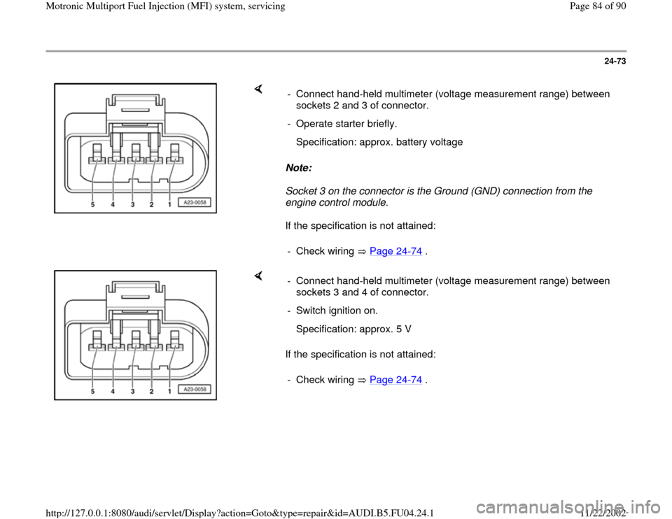
Note:
Socket 3 on the connector is the Ground (GND) connection from the
engine control module.
If the specification is not attained: - Connect hand-held multimeter (voltage measurement range) between
sockets 2 and 3 of connector.
- Operate starter briefly.
Specification: approx. battery voltage
- Check wiring Page 24
-74
.
If the specification is not attained: - Connect hand-held multimeter (voltage measurement range) between
sockets 3 and 4 of connector.
- Switch ignition on.
Specification: approx. 5 V
- Check wiring Page 24
-74
.
Pa
ge 84 of 90 Motronic Multi
port Fuel In
jection
(MFI
) system, servicin
g
11/22/2002 htt
p://127.0.0.1:8080/audi/servlet/Dis
play?action=Goto&t
yp
e=re
pair&id=AUDI.B5.FU04.24.1