engine AUDI A4 1996 B5 / 1.G APB Engine Motronic Syst
[x] Cancel search | Manufacturer: AUDI, Model Year: 1996, Model line: A4, Model: AUDI A4 1996 B5 / 1.GPages: 166, PDF Size: 0.53 MB
Page 13 of 166
01-11
- If no display appears, check diagnostic
cables:
Electrical Wiring Diagrams, Troubleshooting &
Component Locations Depending on the function required:
- Switch ignition on.
or
Start engine Page 01
-6 , table of available
functions.
- Switch on printer with PRINT button (indicator
light in button lights up).
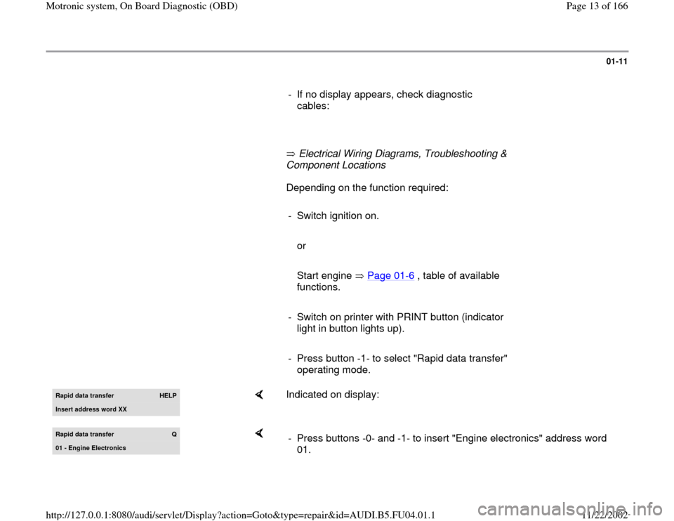
- Press button -1- to select "Rapid data transfer"
operating mode. Rapid data transfer
HELP
Insert address word XX
Indicated on display:
Rapid data transfer
Q
01 - En
gine Electronics
- Press buttons -0- and -1- to insert "Engine electronics" address word
01.
Pa
ge 13 of 166 Motronic s
ystem, On Board Dia
gnostic
(OBD
)
11/22/2002 htt
p://127.0.0.1:8080/audi/servlet/Dis
play?action=Goto&t
yp
e=re
pair&id=AUDI.B5.FU04.01.1
Page 16 of 166
01-13
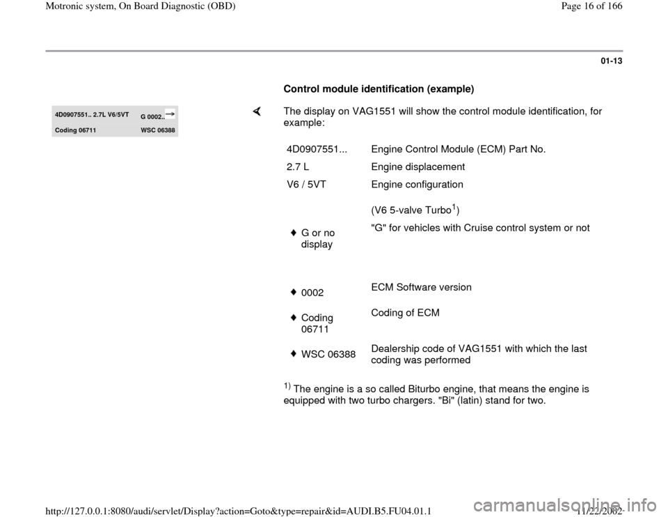
Control module identification (example) 4D0907551.. 2.7L V6/5VT
G 0002..
Codin
g 06711
WSC 06388
The display on VAG1551 will show the control module identification, for
example: 1)
The engine is a so called Biturbo engine, that means the engine is
equipped with two turbo chargers. "Bi" (latin) stand for two. 4D0907551... Engine Control Module (ECM) Part No.
2.7 L Engine displacement
V6 / 5VT Engine configuration
(V6 5-valve Turbo
1)
G or no
display "G" for vehicles with Cruise control system or not 0002ECM Software version Coding
06711 Coding of ECM WSC 06388Dealership code of VAG1551 with which the last
coding was performed
Pa
ge 16 of 166 Motronic s
ystem, On Board Dia
gnostic
(OBD
)
11/22/2002 htt
p://127.0.0.1:8080/audi/servlet/Dis
play?action=Goto&t
yp
e=re
pair&id=AUDI.B5.FU04.01.1
Page 17 of 166
01-14
If the coding differs from the vehicle version,
then:
- Check coding of engine control module Page
01
-93
, Coding engine control module.
-
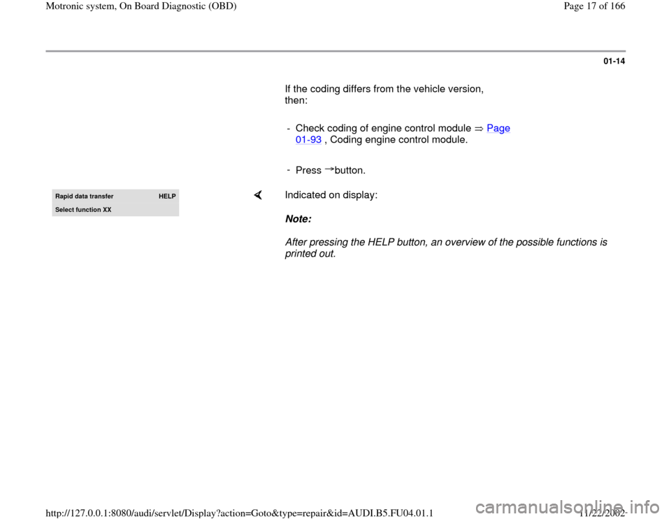
Press button.Rapid data transfer
HELP
Select function XX
Indicated on display:
Note:
After pressing the HELP button, an overview of the possible functions is
printed out.
Pa
ge 17 of 166 Motronic s
ystem, On Board Dia
gnostic
(OBD
)
11/22/2002 htt
p://127.0.0.1:8080/audi/servlet/Dis
play?action=Goto&t
yp
e=re
pair&id=AUDI.B5.FU04.01.1
Page 18 of 166
01-15
Diagnostic Trouble Code (DTC) Memory,
checking and erasing
- Connect vehicle diagnostic, testing and
information system VAS5051 or VAG1551 scan
tool and select "Engine Electronics" by entering
address word 01 Page 01
-9. When doing this
the engine must be idling.
Only if engine does not start:
- Check engine with ignition switched on.
- Switch on printer with PRINT button (indicator
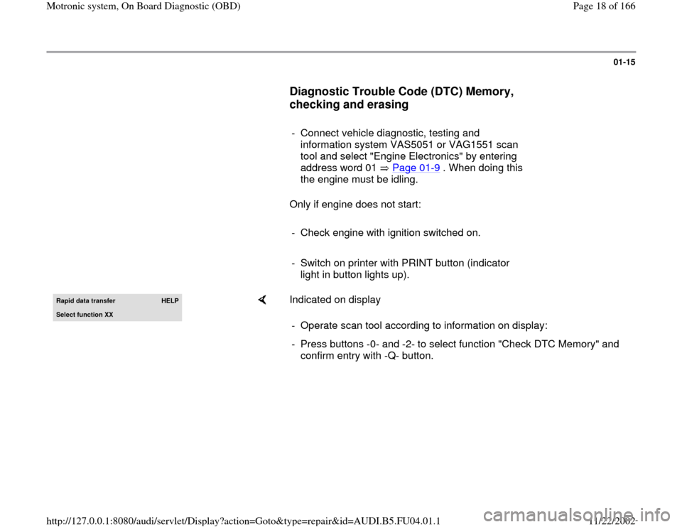
light in button lights up). Rapid data transfer
HELP
Select function XX
Indicated on display
- Operate scan tool according to information on display:
- Press buttons -0- and -2- to select function "Check DTC Memory" and
confirm entry with -Q- button.
Pa
ge 18 of 166 Motronic s
ystem, On Board Dia
gnostic
(OBD
)
11/22/2002 htt
p://127.0.0.1:8080/audi/servlet/Dis
play?action=Goto&t
yp
e=re
pair&id=AUDI.B5.FU04.01.1
Page 22 of 166
01-19
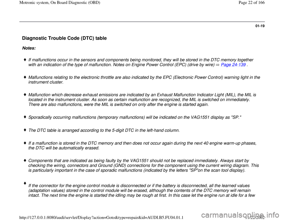
Diagnostic Trouble Code (DTC) table
Notes:
If malfunctions occur in the sensors and components being monitored, they will be stored in the DTC memory together
with an indication of the type of malfunction. Notes on Engine Power Control (EPC) (drive by wire) Page 24
-139
.
Malfunctions relating to the electronic throttle are also indicated by the EPC (Electronic Power Control) warning light in the
instrument cluster.
Malfunction which decrease exhaust emissions are indicated by an Exhaust Malfunction Indicator Light (MIL), the MIL is
located in the instrument cluster. As soon as certain malfunction are recognized, the MIL is switched on immediately.
There are also malfunctions, were the MIL is switched on only after the engine is started again.
Sporadically occurring malfunctions (temporary malfunctions) will be indicated on the VAG1551 display as "SP."
The DTC table is arranged according to the 5-digit DTC in the left-hand column.
If a malfunction is stored in the DTC memory and then does not occur again during the next 40 engine warm-up phases,
the DTC will be automatically erased.
Components that are indicated as being faulty by the VAG1551 should not be replaced immediately. Always start by
checking the wiring, connectors and Ground (GND) connections for the component using the current wiring diagram. This
is particularly important in the case of sporadic malfunctions (indicated by the letters "SP"on the scan tool display).
If the connector for the engine control module is disconnected or if the battery is disconnected, all the learned values
(adaptation values) stored in the control module will be erased, although the contents of the DTC memory will remain
intact. The next time the engine is started the idling may be rough at first. In this case let the engine run at idle for a few
Pa
ge 22 of 166 Motronic s
ystem, On Board Dia
gnostic
(OBD
)
11/22/2002 htt
p://127.0.0.1:8080/audi/servlet/Dis
play?action=Goto&t
yp
e=re
pair&id=AUDI.B5.FU04.01.1
Page 24 of 166
01-20
DTC
Description of malfunction
Corrective action
SAE
VAG
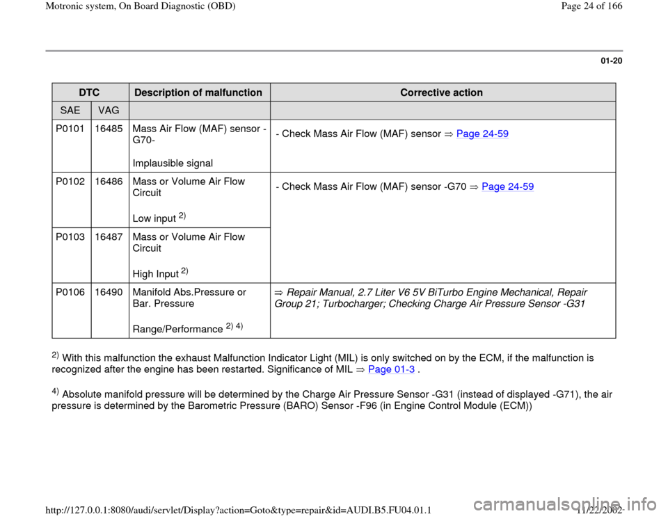
P0101 16485 Mass Air Flow (MAF) sensor -
G70-
Implausible signal - Check Mass Air Flow (MAF) sensor Page 24
-59
P0102 16486 Mass or Volume Air Flow
Circuit
Low input
2) - Check Mass Air Flow (MAF) sensor -G70 Page 24
-59
P0103 16487 Mass or Volume Air Flow
Circuit
High Input
2)
P0106 16490 Manifold Abs.Pressure or
Bar. Pressure
Range/Performance
2) 4)
Repair Manual, 2.7 Liter V6 5V BiTurbo Engine Mechanical, Repair
Group 21; Turbocharger; Checking Charge Air Pressure Sensor -G31
2) With this malfunction the exhaust Malfunction Indicator Light (MIL) is only switched on by the ECM, if the malfunction is
recognized after the engine has been restarted. Significance of MIL Page 01
-3 .
4) Absolute manifold pressure will be determined by the Charge Air Pressure Sensor -G31 (instead of displayed -G71), the air
pressure is determined by the Barometric Pressure (BARO) Sensor -F96 (in Engine Control Module (ECM))
Pa
ge 24 of 166 Motronic s
ystem, On Board Dia
gnostic
(OBD
)
11/22/2002 htt
p://127.0.0.1:8080/audi/servlet/Dis
play?action=Goto&t
yp
e=re
pair&id=AUDI.B5.FU04.01.1
Page 25 of 166
01-21
DTC
Description of malfunction
Corrective action
SAE
VAG
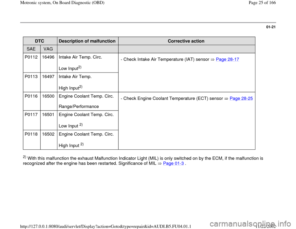
P0112 16496 Intake Air Temp. Circ.
Low Input
2) - Check Intake Air Temperature (IAT) sensor Page 28
-17
P0113 16497 Intake Air Temp.
High Input
2)
P0116 16500 Engine Coolant Temp. Circ.
Range/Performance - Check Engine Coolant Temperature (ECT) sensor Page 28
-25
P0117 16501 Engine Coolant Temp. Circ.
Low Input
2)
P0118 16502 Engine Coolant Temp. Circ.
High Input 2)
2) With this malfunction the exhaust Malfunction Indicator Light (MIL) is only switched on by the ECM, if the malfunction is
recognized after the engine has been restarted. Significance of MIL Page 01
-3 .
Pa
ge 25 of 166 Motronic s
ystem, On Board Dia
gnostic
(OBD
)
11/22/2002 htt
p://127.0.0.1:8080/audi/servlet/Dis
play?action=Goto&t
yp
e=re
pair&id=AUDI.B5.FU04.01.1
Page 26 of 166
01-22
DTC
Description of malfunction
Corrective action
SAE
VAG
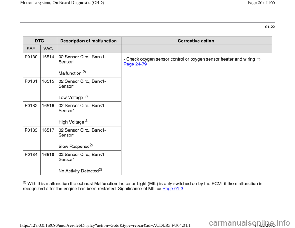
P0130 16514 02 Sensor Circ., Bank1-
Sensor1
Malfunction
2) - Check oxygen sensor control or oxygen sensor heater and wiring
Page 24
-79
P0131 16515 02 Sensor Circ., Bank1-
Sensor1
Low Voltage
2)
P0132 16516 02 Sensor Circ., Bank1-
Sensor1
High Voltage 2)
P0133 16517 02 Sensor Circ., Bank1-
Sensor1
Slow Response2)
P0134 16518 02 Sensor Circ., Bank1-
Sensor1
No Activity Detected
2)
2) With this malfunction the exhaust Malfunction Indicator Light (MIL) is only switched on by the ECM, if the malfunction is
recognized after the engine has been restarted. Significance of MIL Page 01
-3 .
Pa
ge 26 of 166 Motronic s
ystem, On Board Dia
gnostic
(OBD
)
11/22/2002 htt
p://127.0.0.1:8080/audi/servlet/Dis
play?action=Goto&t
yp
e=re
pair&id=AUDI.B5.FU04.01.1
Page 27 of 166
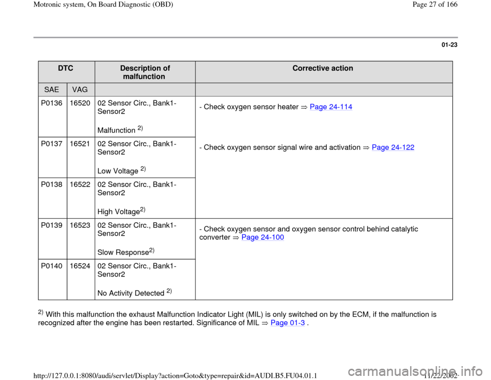
01-23
DTC
Description of
malfunction
Corrective action
SAE
VAG
P0136 16520 02 Sensor Circ., Bank1-
Sensor2
Malfunction
2) - Check oxygen sensor heater Page 24
-114
P0137 16521 02 Sensor Circ., Bank1-
Sensor2
Low Voltage
2) - Check oxygen sensor signal wire and activation Page 24
-122
P0138 16522 02 Sensor Circ., Bank1-
Sensor2
High Voltage
2)
P0139 16523 02 Sensor Circ., Bank1-
Sensor2
Slow Response2) - Check oxygen sensor and oxygen sensor control behind catalytic
converter Page 24
-100
P0140 16524 02 Sensor Circ., Bank1-
Sensor2
No Activity Detected
2)
2) With this malfunction the exhaust Malfunction Indicator Light (MIL) is only switched on by the ECM, if the malfunction is
recognized after the engine has been restarted. Significance of MIL Page 01
-3 .
Pa
ge 27 of 166 Motronic s
ystem, On Board Dia
gnostic
(OBD
)
11/22/2002 htt
p://127.0.0.1:8080/audi/servlet/Dis
play?action=Goto&t
yp
e=re
pair&id=AUDI.B5.FU04.01.1
Page 28 of 166
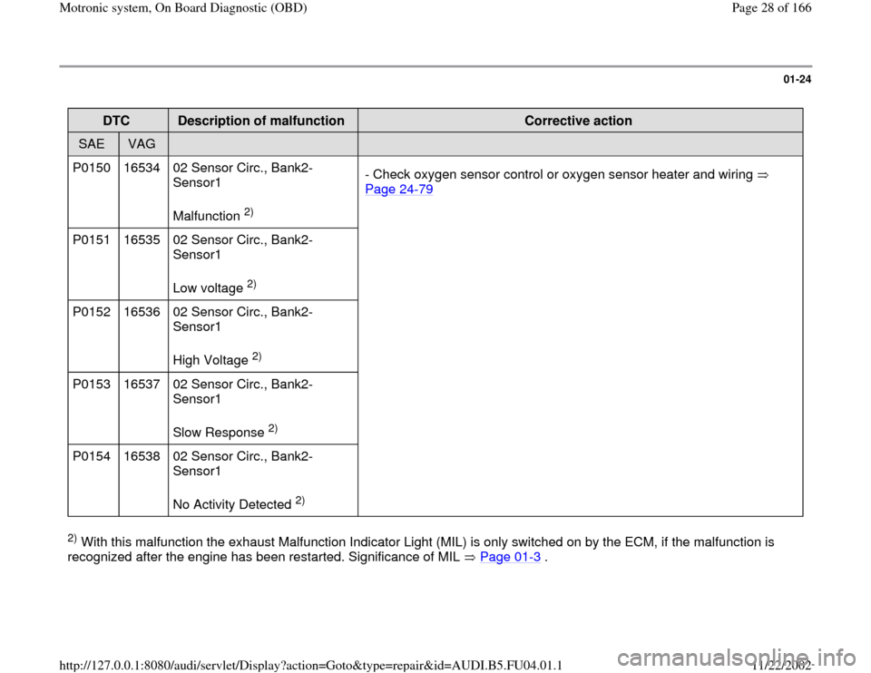
01-24
DTC
Description of malfunction
Corrective action
SAE
VAG
P0150 16534 02 Sensor Circ., Bank2-
Sensor1
Malfunction
2) - Check oxygen sensor control or oxygen sensor heater and wiring
Page 24
-79
P0151 16535 02 Sensor Circ., Bank2-
Sensor1
Low voltage
2)
P0152 16536 02 Sensor Circ., Bank2-
Sensor1
High Voltage 2)
P0153 16537 02 Sensor Circ., Bank2-
Sensor1
Slow Response 2)
P0154 16538 02 Sensor Circ., Bank2-
Sensor1
No Activity Detected
2)
2) With this malfunction the exhaust Malfunction Indicator Light (MIL) is only switched on by the ECM, if the malfunction is
recognized after the engine has been restarted. Significance of MIL Page 01
-3 .
Pa
ge 28 of 166 Motronic s
ystem, On Board Dia
gnostic
(OBD
)
11/22/2002 htt
p://127.0.0.1:8080/audi/servlet/Dis
play?action=Goto&t
yp
e=re
pair&id=AUDI.B5.FU04.01.1