engine AUDI A4 1996 B5 / 1.G ATW Engine Motronic Fuel Injection Syst
[x] Cancel search | Manufacturer: AUDI, Model Year: 1996, Model line: A4, Model: AUDI A4 1996 B5 / 1.GPages: 81, PDF Size: 1.03 MB
Page 20 of 81
24-19
Wiring and component testing using
VAG1598/31 test box
Note:
VAG1598/31 test box is designed so that it can
be simultaneously connected to the wiring
harness at the Engine Control Module (ECM)
and also to the ECM itself.
This is advantageous because electronic
engine control remains fully functional (e.g.
measurement of signals with engine running)
when the test box is attached.
Relevant test procedures note whether Engine
Control Module (ECM) should also be
connected to the test box or not.
Always use VAG1594A connector test kit to
attach measurement devices (e.g. VAG1527B
voltage tester, VAG1526 multimeter etc.).
WARNING!
To avoid damaging electronic components,
set measuring range before connecting test
leads and observe all test requirements.
Pa
ge 20 of 81 Motronic fuel in
jection s
ystem, servicin
g
11/21/2002 htt
p://127.0.0.1:8080/audi/servlet/Dis
play?action=Goto&t
yp
e=re
pair&id=AUDI.B5.FU06.24.1
Page 21 of 81
24-20
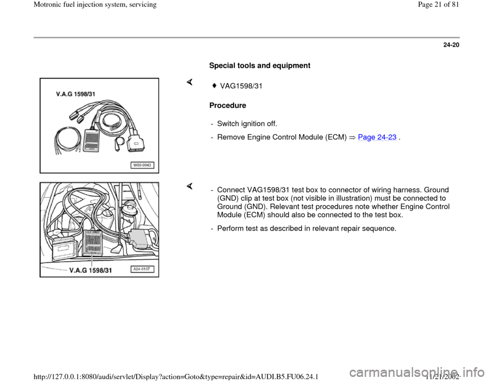
Special tools and equipment
Procedure
VAG1598/31
- Switch ignition off.
- Remove Engine Control Module (ECM) Page 24
-23
.
- Connect VAG1598/31 test box to connector of wiring harness. Ground
(GND) clip at test box (not visible in illustration) must be connected to
Ground (GND). Relevant test procedures note whether Engine Control
Module (ECM) should also be connected to the test box.
- Perform test as described in relevant repair sequence.
Pa
ge 21 of 81 Motronic fuel in
jection s
ystem, servicin
g
11/21/2002 htt
p://127.0.0.1:8080/audi/servlet/Dis
play?action=Goto&t
yp
e=re
pair&id=AUDI.B5.FU06.24.1
Page 22 of 81
24-21
Note:
Important note:
After re-connecting the Engine Control Module
(ECM), the following work steps must be
performed:
- Perform adaptation of the Throttle Valve Control
Module -J338- Page 24
-121
.
- For vehicles with automatic transmission, the
kick down function must be adapted Page 24
-
139
.
- Check DTC memory and erase it if necessary
Page 01
-16
.
- If DTC memory was erased, readiness code
must be re-generated Page 01
-73
.
Note:
During the first adaptation phase, it is possible
that idle will be rough and vehicle may shake
lightly in drive mode.
Pa
ge 22 of 81 Motronic fuel in
jection s
ystem, servicin
g
11/21/2002 htt
p://127.0.0.1:8080/audi/servlet/Dis
play?action=Goto&t
yp
e=re
pair&id=AUDI.B5.FU06.24.1
Page 24 of 81
24-23
Engine Control Module (ECM), replacing
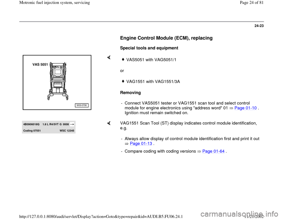
Special tools and equipment
or
Removing
VAS5051 with VAG5051/1VAG1551 with VAG1551/3A
- Connect VAS5051 tester or VAG1551 scan tool and select control
module for engine electronics using "address word" 01 Page 01
-10
.
Ignition must remain switched on.
4B0906018Q
1.8 L R4/5VT
G 0008
Codin
g 07551
WSC 12345
VAG1551 Scan Tool (ST) display indicates control module identification,
e.g.
- Always allow display of control module identification first and print it out
Page 01
-13
.
- Compare coding with coding versions Page 01
-64
.
Pa
ge 24 of 81 Motronic fuel in
jection s
ystem, servicin
g
11/21/2002 htt
p://127.0.0.1:8080/audi/servlet/Dis
play?action=Goto&t
yp
e=re
pair&id=AUDI.B5.FU06.24.1
Page 26 of 81
24-25
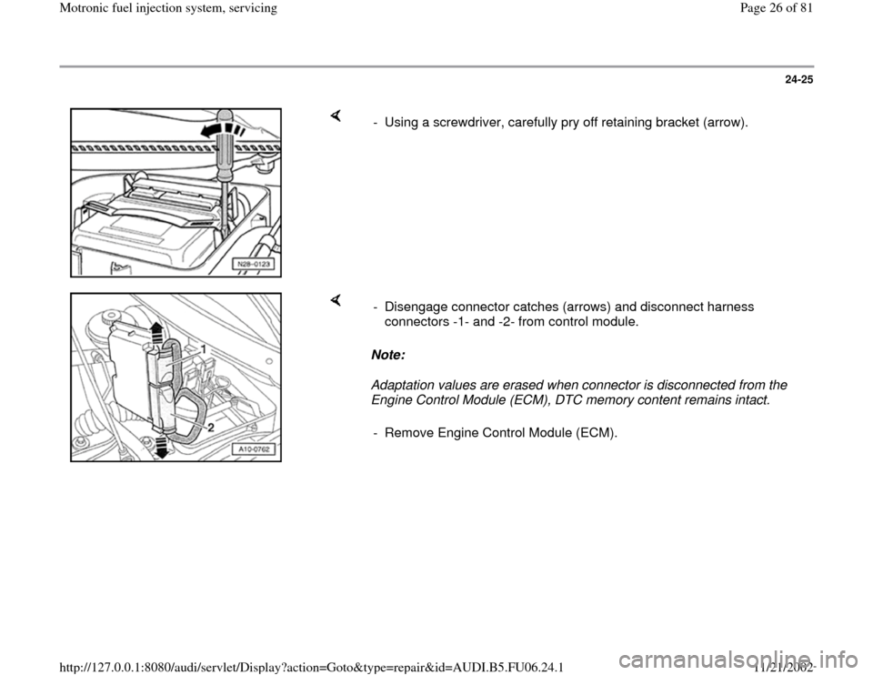
- Using a screwdriver, carefully pry off retaining bracket (arrow).
Note:
Adaptation values are erased when connector is disconnected from the
Engine Control Module (ECM), DTC memory content remains intact. - Disengage connector catches (arrows) and disconnect harness
connectors -1- and -2- from control module.
- Remove Engine Control Module (ECM).
Pa
ge 26 of 81 Motronic fuel in
jection s
ystem, servicin
g
11/21/2002 htt
p://127.0.0.1:8080/audi/servlet/Dis
play?action=Goto&t
yp
e=re
pair&id=AUDI.B5.FU06.24.1
Page 27 of 81
24-26
Installing
Installation is reverse of removal, noting the
following:
Note:
Important note:
After installing new Engine Control Module
(ECM), the following work steps must be
performed:
- Check DTC memory and erase it if necessary
Page 01
-16
.
- Perform adaptation of the Throttle Valve Control
Module -J338- Page 24
-121
.
- Observe notes for coding new Engine Control
Module (ECM) Page 01
-62
.
- For vehicles with cruise control (discernable at
steering column), switch this free in ECM:
Repair Manual, Electrical Equipment On
Board Diagnostic (OBD), Repair Group 01; OBD for cruise control system
- For vehicles with automatic transmission, the
kick down function must be adapted Page 24
-
Pa
ge 27 of 81 Motronic fuel in
jection s
ystem, servicin
g
11/21/2002 htt
p://127.0.0.1:8080/audi/servlet/Dis
play?action=Goto&t
yp
e=re
pair&id=AUDI.B5.FU06.24.1
Page 29 of 81
24-27
- Adapt immobilizer to Engine Control Module
(ECM):
Repair Manual, Electrical Equipment On
Board Diagnostic (OBD), Repair Group 01; OBD of immobilizer
- variable code; adaptation after
replacing Engine Control Module (ECM)
- Generate readiness code Page 01
-73
.
Note:
During the first adaptation phase, it is possible
that idle will be rough and vehicle may shake
lightly in drive mode.
Pa
ge 29 of 81 Motronic fuel in
jection s
ystem, servicin
g
11/21/2002 htt
p://127.0.0.1:8080/audi/servlet/Dis
play?action=Goto&t
yp
e=re
pair&id=AUDI.B5.FU06.24.1
Page 31 of 81
24-29
Note:
Idle speed cannot be adjusted.
Idle speed is checked during basic setting of
the engine.
During basic setting, the Evaporative Emission
(EVAP) canister purge regulator valve (EVAP
valve -N80-) is closed and the A/C compressor
is switched off
Test sequence
- Check DTC memory Page 01
-16
. There must
not be any DTCs stored, repair malfunctions if
necessary, erase DTC memory, switch engine
off and start again, road test vehicle and check
DTC memory again as a control measure.
- Let engine continue to run at idle.
WARNING!
The electric fan for the radiator must not be
running. Rapid data transfer
HELP
Select function XX
When indicated on display
-
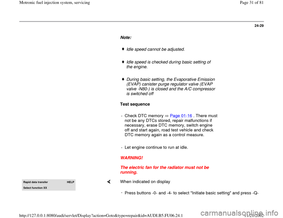
Press buttons -0- and -4- to select "Initiate basic setting" and press -Q-
Pa
ge 31 of 81 Motronic fuel in
jection s
ystem, servicin
g
11/21/2002 htt
p://127.0.0.1:8080/audi/servlet/Dis
play?action=Goto&t
yp
e=re
pair&id=AUDI.B5.FU06.24.1
Page 33 of 81
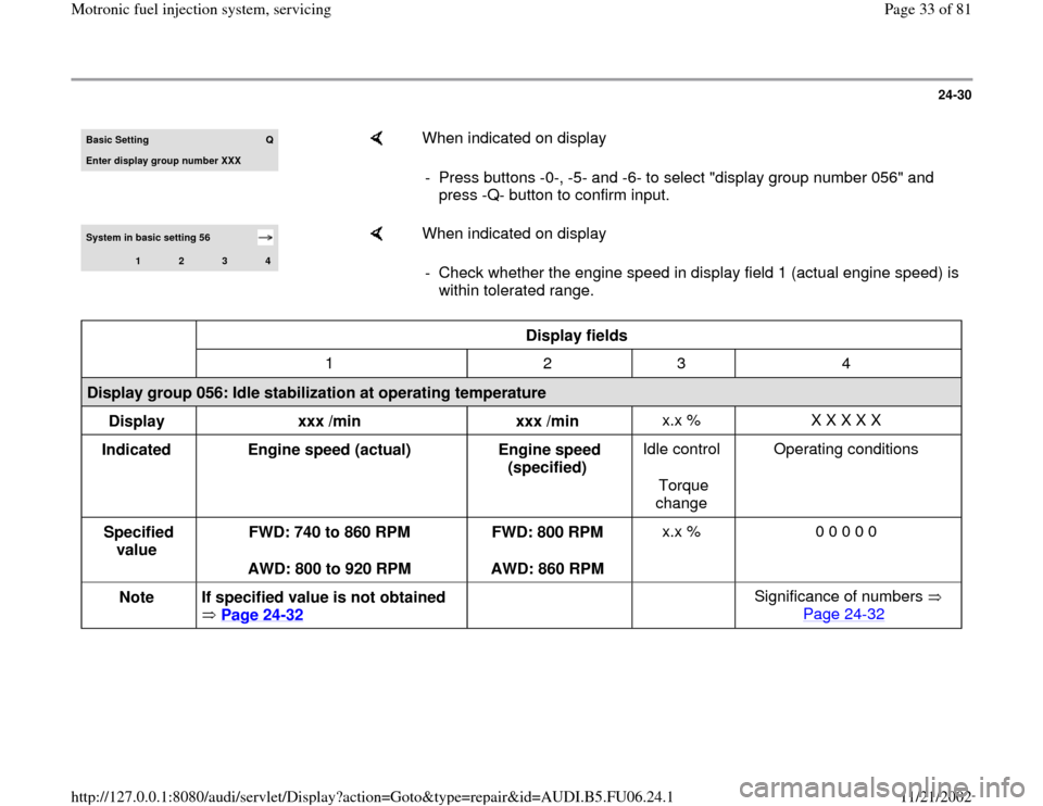
24-30
Basic Settin
g
Q
Enter display group number XXX
When indicated on display
- Press buttons -0-, -5- and -6- to select "display group number 056" and
press -Q- button to confirm input.
System in basic setting 56
1
2
3
4
When indicated on display
- Check whether the engine speed in display field 1 (actual engine speed) is
within tolerated range.
Display fields
1 2 3 4
Display group 056: Idle stabilization at operating temperature
Display
xxx /min
xxx /min x.x % X X X X X
Indicated
Engine speed (actual)
Engine speed
(specified) Idle control
Torque
change Operating conditions
Specified
value FWD: 740 to 860 RPM
AWD: 800 to 920 RPM FWD: 800 RPM
AWD: 860 RPM x.x % 0 0 0 0 0
Note
If specified value is not obtained
Page 24
-32
Significance of numbers
Page 24
-32
Pa
ge 33 of 81 Motronic fuel in
jection s
ystem, servicin
g
11/21/2002 htt
p://127.0.0.1:8080/audi/servlet/Dis
play?action=Goto&t
yp
e=re
pair&id=AUDI.B5.FU06.24.1
Page 34 of 81
24-31
Note:
Engine speed in display field 1 (actual engine
speed) is the current engine speed.
Engine speed in display field 2 (specified
engine speed) is a theoretical engine speed
calculated by the ECM.
At idle, the ECM always attempts to adapt the
engine speed (actual) to the specified engine
speed (specified).
This means that the engine speed (actual) must
always approximately match the engine speed
(specified) at idle.
Display fields 3 and 4 provide information, but
are not relevant for checking idle speed.
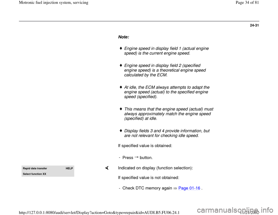
If specified value is obtained:
-
Press button.
Rapid data transfer
HELP
Select function XX
Indicated on display (function selection):
If specified value is not obtained:
- Check DTC memory again Page 01
-16
.
Pa
ge 34 of 81 Motronic fuel in
jection s
ystem, servicin
g
11/21/2002 htt
p://127.0.0.1:8080/audi/servlet/Dis
play?action=Goto&t
yp
e=re
pair&id=AUDI.B5.FU06.24.1