26-pin AUDI A4 1996 B5 / 1.G Instrument Cluster Location Diagram Through Model Year 1999 Workshop Manual

AUDI A4 1996 B5 / 1.G Instrument Cluster Location Diagram Through Model Year 1999 Workshop Manual A4 1996 B5 / 1.G AUDI AUDI https://www.carmanualsonline.info/img/6/914/w960_914-0.png AUDI A4 1996 B5 / 1.G Instrument Cluster Location Diagram Through Model Year 1999 Workshop Manual

Page 9 of 27
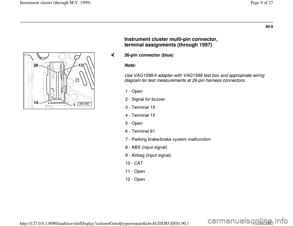
AUDI A4 1996 B5 / 1.G Instrument Cluster Location Diagram Through Model Year 1999 Workshop Manual 90-9
      
Instrument cluster multi-pin connector, 
terminal assignments (through 1997)
 
    
26-pin connector (blue)  
Note:  
Use VAG1598/4 adapter with VAG1598 test box and appropriate wiring 
di

Page 11 of 27

AUDI A4 1996 B5 / 1.G Instrument Cluster Location Diagram Through Model Year 1999 Workshop Manual 90-11
 
    
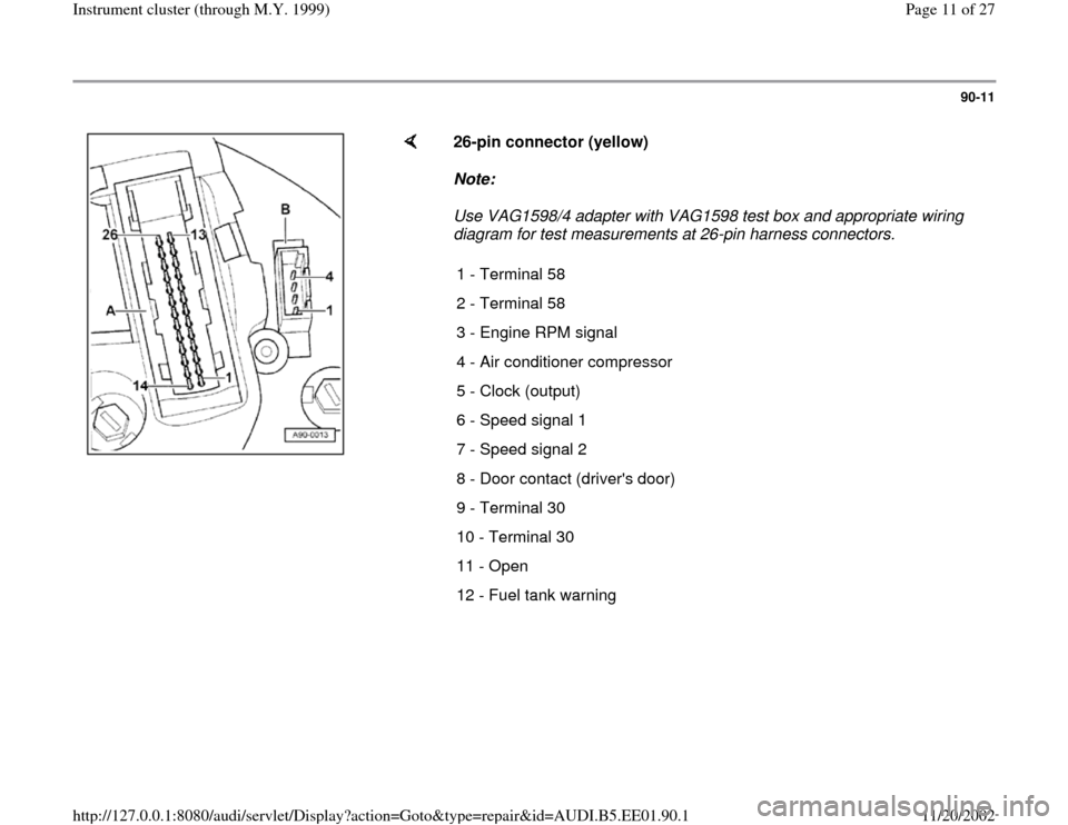
26-pin connector (yellow)  
Note:  
Use VAG1598/4 adapter with VAG1598 test box and appropriate wiring 
diagram for test measurements at 26-pin harness connectors. 
1 - Terminal 58
2 - Te

Page 24 of 27

AUDI A4 1996 B5 / 1.G Instrument Cluster Location Diagram Through Model Year 1999 Workshop Manual 90-22
      
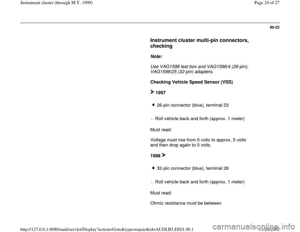
Instrument cluster multi-pin connectors, 
checking
 
     
Note:  
     Use VAG1598 test box and VAG1598/4 (26-pin), 
VAG1598/25 (32-pin) adapters. 
     
Checking Vehicle Speed Sensor (V

Page 26 of 27

AUDI A4 1996 B5 / 1.G Instrument Cluster Location Diagram Through Model Year 1999 Workshop Manual 90-23
      
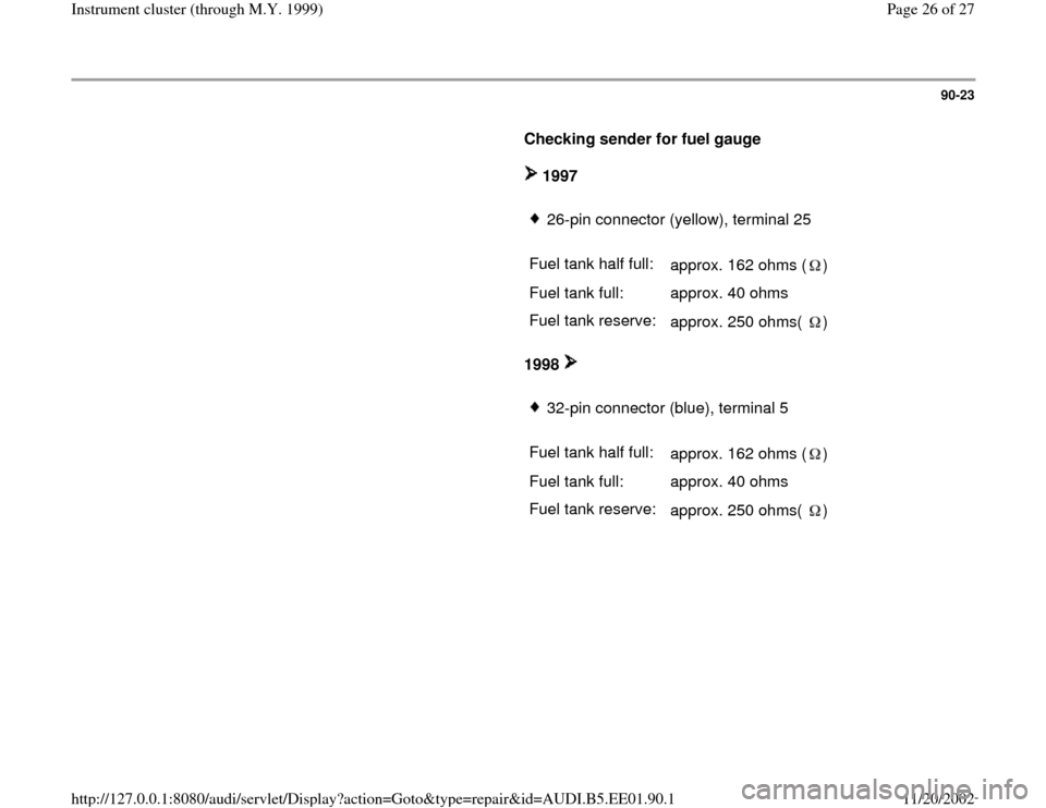
Checking sender for fuel gauge  
     
 1997       
26-pin connector (yellow), terminal 25
     
Fuel tank half full:  
approx. 162 ohms ( )  
Fuel tank full:   approx. 40 ohms  
Fuel tan

Page 27 of 27

AUDI A4 1996 B5 / 1.G Instrument Cluster Location Diagram Through Model Year 1999 Workshop Manual 90-24
      
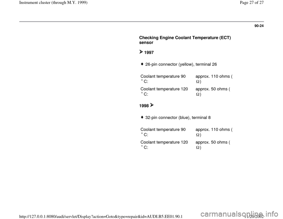
Checking Engine Coolant Temperature (ECT) 
sensor  
     
 1997       
26-pin connector (yellow), terminal 26
     
Coolant temperature 90
C:  
approx. 110 ohms (
)  
Coolant temperature