AUDI A4 1996 B5 / 1.G Suspension Lower Guide Link Remove And Install Workshop Manual
Manufacturer: AUDI, Model Year: 1996,
Model line: A4,
Model: AUDI A4 1996 B5 / 1.G
Pages: 6, PDF Size: 0.12 MB
AUDI A4 1996 B5 / 1.G Suspension Lower Guide Link Remove And Install Workshop Manual
A4 1996 B5 / 1.G
AUDI
AUDI
https://www.carmanualsonline.info/img/6/1161/w960_1161-0.png
AUDI A4 1996 B5 / 1.G Suspension Lower Guide Link Remove And Install Workshop Manual
Trending: AUX, tow, light, wheel, air suspension, torque, brake light
Page 1 of 6
40-97
Lower guide link, removing
and installing
Removing
- Remove wheel trim.
On light alloy wheels use puller in vehicle tool kit
to remove trim cap.
- Remove wheel.
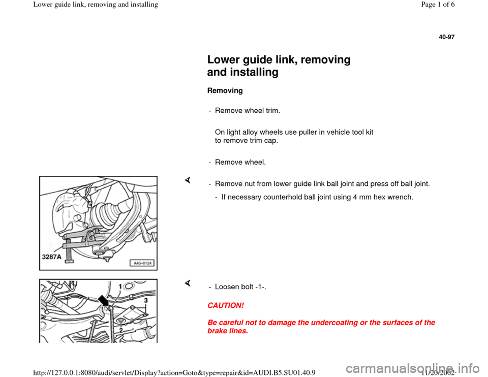
- Remove nut from lower guide link ball joint and press off ball joint.
- If necessary counterhold ball joint using 4 mm hex wrench.
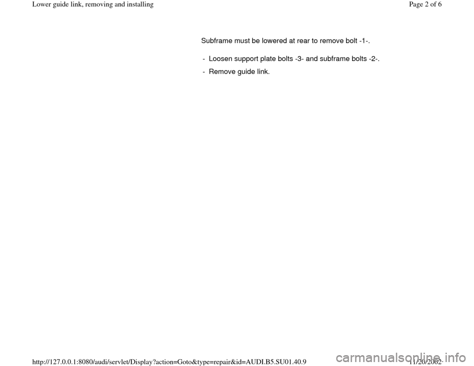
CAUTION!
Be careful not to damage the undercoating or the surfaces of the
brake lines. - Loosen bolt -1-.
Pa
ge 1 of 6 Lower
guide link, removin
g and installin
g
11/20/2002 htt
p://127.0.0.1:8080/audi/servlet/Dis
play?action=Goto&t
yp
e=re
pair&id=AUDI.B5.SU01.40.9
Page 2 of 6
Subframe must be lowered at rear to remove bolt -1-.
- Loosen support plate bolts -3- and subframe bolts -2-.
- Remove guide link.
Pa
ge 2 of 6 Lower
guide link, removin
g and installin
g
11/20/2002 htt
p://127.0.0.1:8080/audi/servlet/Dis
play?action=Goto&t
yp
e=re
pair&id=AUDI.B5.SU01.40.9
Page 3 of 6
40-98
Installing
CAUTION!
The bonded rubber bushings can only be
turned to a limited extent. The bolted
connections on the suspension links should
therefore only be tightened when the vehicle
is standing on the ground.
All nuts and bolts must be replaced
When installing pay particular attention to the
following points:
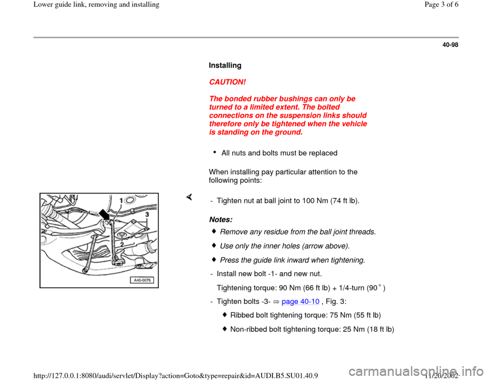
Notes: - Tighten nut at ball joint to 100 Nm (74 ft lb).
Remove any residue from the ball joint threads.Use only the inner holes (arrow above).Press the guide link inward when tightening.
- Install new bolt -1- and new nut.
Tightening torque: 90 Nm (66 ft lb) + 1/4-turn (90 )
- Tighten bolts -3- page 40
-10
, Fig. 3:
Ribbed bolt tightening torque: 75 Nm (55 ft lb)
Non-ribbed bolt tightening torque: 25 Nm (18 ft lb)
Pa
ge 3 of 6 Lower
guide link, removin
g and installin
g
11/20/2002 htt
p://127.0.0.1:8080/audi/servlet/Dis
play?action=Goto&t
yp
e=re
pair&id=AUDI.B5.SU01.40.9
Page 4 of 6
- Install new subframe bolts -2- and tighten to 110 Nm (81 ft lb) + 1/4-
turn (90 )
Pa
ge 4 of 6 Lower
guide link, removin
g and installin
g
11/20/2002 htt
p://127.0.0.1:8080/audi/servlet/Dis
play?action=Goto&t
yp
e=re
pair&id=AUDI.B5.SU01.40.9
Page 5 of 6
40-99
Lower guide link hydraulic bushings,
replacing
Special tools, test equipment and auxiliary
items
3346/2 3301 3347
3347/1 3346/2 3347/2
3346/3
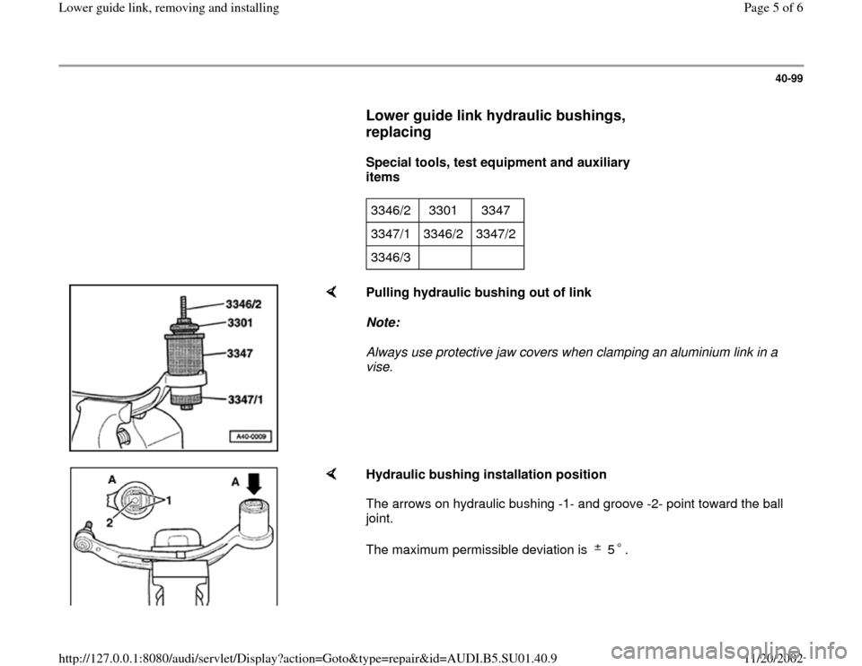
Pulling hydraulic bushing out of link
Note:
Always use protective jaw covers when clamping an aluminium link in a
vise.
Hydraulic bushing installation position
The arrows on hydraulic bushing -1- and groove -2- point toward the ball
joint.
The maximum permissible deviation is 5 .
Pa
ge 5 of 6 Lower
guide link, removin
g and installin
g
11/20/2002 htt
p://127.0.0.1:8080/audi/servlet/Dis
play?action=Goto&t
yp
e=re
pair&id=AUDI.B5.SU01.40.9
Page 6 of 6
40-100
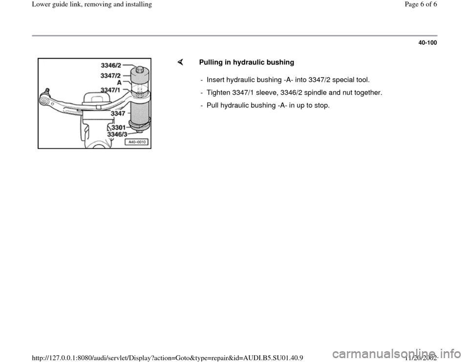
Pulling in hydraulic bushing
- Insert hydraulic bushing -A- into 3347/2 special tool.
- Tighten 3347/1 sleeve, 3346/2 spindle and nut together.
- Pull hydraulic bushing -A- in up to stop.
Pa
ge 6 of 6 Lower
guide link, removin
g and installin
g
11/20/2002 htt
p://127.0.0.1:8080/audi/servlet/Dis
play?action=Goto&t
yp
e=re
pair&id=AUDI.B5.SU01.40.9
Trending: tow, air suspension, brake light, AUX, torque, light, wheel