ignition AUDI A4 1997 B5 / 1.G AEB ATW Engines Charge Air System With Turbocharger Workshop Manual
[x] Cancel search | Manufacturer: AUDI, Model Year: 1997, Model line: A4, Model: AUDI A4 1997 B5 / 1.GPages: 42, PDF Size: 0.54 MB
Page 4 of 42
21-49
Note:
The recirculating valve for turbocharger -N249-
and wire connections are monitored by the
Engine Control Module (ECM).
- Connect VAS5051 tester or VAG1551 scan tool
and select control module for engine electronics
using "address word 01". Engine must run at idle
for this:
Repair Manual, 1.8 Liter 4-Cyl. 5V Turbo Fuel
Injection & Ignition, Repair Group 01 If a malfunction relating to the recirculating valve
for turbocharger -N249- is displayed:
- Disconnect hoses from valve; harness connector
remains connected.
- Attach assisting hose to one connection of
valve.
Pa
ge 4 of 42 Char
ge air s
ystem with turbochar
ger
(en
gine code ATW
)
11/18/2002 htt
p://127.0.0.1:8080/audi/servlet/Dis
play?action=Goto&t
yp
e=re
pair&id=AUDI.B5.GE02.21.3
Page 5 of 42
21-50
- Initiate output Diagnostic Test Mode (DTM) and
activate the recirculating valve for turbocharger -
N249-:
Repair Manual, 1.8 Liter 4-Cyl. 5V Turbo Fuel
Injection & Ignition, Repair Group 01 Output Diagnostic Test Mode Recirc. valve for turbochar
ger -N249
Indicated on display
If valve does not click:
If valve does not open and close properly:
Checking internal resistance Valve must click...
...and must open and close (can be tested by blowing into assisting
hose).
- Check internal resistance of valve.
- Replace recirculating valve for turbocharger -N249-.
- Disconnect harness connector at valve.
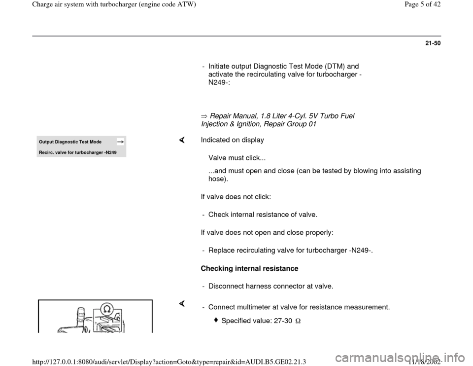
- Connect multimeter at valve for resistance measurement.
Specified value: 27-30
Pa
ge 5 of 42 Char
ge air s
ystem with turbochar
ger
(en
gine code ATW
)
11/18/2002 htt
p://127.0.0.1:8080/audi/servlet/Dis
play?action=Goto&t
yp
e=re
pair&id=AUDI.B5.GE02.21.3
Page 8 of 42
21-52
If LED does not light:
- Check wire connection from terminal 1 to Fuel
Pump (FP) relay via fuse for an open circuit":
Electrical Wiring Diagrams, Troubleshooting &
Component Locations
- Repair open circuit if necessary.
If wire connection is OK:
- Check Fuel Pump (FP) relay:
Repair Manual, 1.8 Liter 4-Cyl. 5V Turbo Fuel
Injection & Ignition, Repair Group 24 If LED lights:
- Check activation:
Checking activation
- Connect VAG1527B voltage tester to connector terminals 1 (B+) and 2.
-
Initiate output Diagnostic Test Mode (DTM) and activate the
Pa
ge 8 of 42 Char
ge air s
ystem with turbochar
ger
(en
gine code ATW
)
11/18/2002 htt
p://127.0.0.1:8080/audi/servlet/Dis
play?action=Goto&t
yp
e=re
pair&id=AUDI.B5.GE02.21.3
Page 9 of 42
Repair Manual, 1.8 Liter 4-Cyl. 5V Turbo Fuel Injection & Ignition,
Repair Group 01 recirculating valve for turbocharger -N249-:
LED must blink.
Pa
ge 9 of 42 Char
ge air s
ystem with turbochar
ger
(en
gine code ATW
)
11/18/2002 htt
p://127.0.0.1:8080/audi/servlet/Dis
play?action=Goto&t
yp
e=re
pair&id=AUDI.B5.GE02.21.3
Page 10 of 42
21-53
If LED does not blink or if it remains constantly
lit:
- Connect VAG1598/31 test box at wiring harness
to ECM, do not connect ECM:
Repair Manual, 1.8 Liter 4-Cyl. 5V Turbo Fuel
Injection & Ignition, Repair Group 24
If wire connection is OK:
Repair Manual, 1.8 Liter 4-Cyl. 5V Turbo Fuel Injection & Ignition,
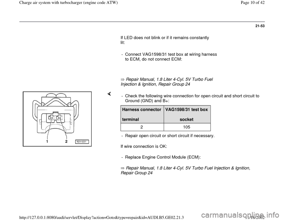
Repair Group 24 - Check the following wire connection for open circuit and short circuit to
Ground (GND) and B+: Harness connector
terminal
VAG1598/31 test box
socket
2 105
- Repair open circuit or short circuit if necessary.
- Replace Engine Control Module (ECM):
Pa
ge 10 of 42 Char
ge air s
ystem with turbochar
ger
(en
gine code ATW
)
11/18/2002 htt
p://127.0.0.1:8080/audi/servlet/Dis
play?action=Goto&t
yp
e=re
pair&id=AUDI.B5.GE02.21.3
Page 12 of 42
21-55
Test requirements
All hoses and wires have been checked for
proper seating and seal.
DTC memory checked
Repair Manual, 1.8 Liter 4-Cyl. 5V Turbo Fuel
Injection & Ignition, Repair Group 01
Output Diagnostic Test Mode (DTM)
performed
Repair Manual, 1.8 Liter 4-Cyl. 5V Turbo Fuel
Injection & Ignition, Repair Group 01
Vehicle tester VAS 5051 or VAG 1551
connected.
Test sequence
WARNING!
To reduce the risk of accident or injury while
carrying out tests and measurements during
a road test, observe safety precautions
Page 21
-40
.
Pa
ge 12 of 42 Char
ge air s
ystem with turbochar
ger
(en
gine code ATW
)
11/18/2002 htt
p://127.0.0.1:8080/audi/servlet/Dis
play?action=Goto&t
yp
e=re
pair&id=AUDI.B5.GE02.21.3
Page 16 of 42
21-58
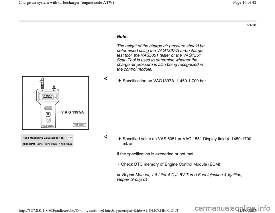
Note:
The height of the charge air pressure should be
determined using the VAG1397/A turbocharger
test tool, the VAS5051 tester or the VAG1551
Scan Tool is used to determine whether the
charge air pressure is also being recognized in
the control module.
Specification on VAG1397A: 1.450-1.700 bar
Read Measuring Value Block 115 3000 RPM
42%
1770 mbar
1770 mbar
If the specification is exceeded or not met:
Repair Manual, 1.8 Liter 4-Cyl. 5V Turbo Fuel Injection & Ignition,
Repair Group 01
Specified value on VAS 5051 or VAG 1551 Display field 4: 1450-1700
mbar
- Check DTC memory of Engine Control Module (ECM):
Pa
ge 16 of 42 Char
ge air s
ystem with turbochar
ger
(en
gine code ATW
)
11/18/2002 htt
p://127.0.0.1:8080/audi/servlet/Dis
play?action=Goto&t
yp
e=re
pair&id=AUDI.B5.GE02.21.3
Page 19 of 42
21-61
Note:
The wastegate bypass regulator valve -N75- and
wire connections are monitored by the Engine
Control Module (ECM).
- Connect VAS5051 tester or VAG1551 scan tool
and select control module for engine electronics
using "address word 01". Engine must run at idle
for this:
Repair Manual, 1.8 Liter 4-Cyl. 5V Turbo Fuel
Injection & Ignition, Repair Group 01
- Check DTC memory of Engine Control Module
(ECM):
Repair Manual, 1.8 Liter 4-Cyl. 5V Turbo Fuel
Injection & Ignition, Repair Group 01 If a malfunction relating to the wastegate bypass
regulator valve -N75- is indicated:
- Disconnect hoses from valve; harness connector
remains connected.
-
Attach assisting hose to one connection of
Pa
ge 19 of 42 Char
ge air s
ystem with turbochar
ger
(en
gine code ATW
)
11/18/2002 htt
p://127.0.0.1:8080/audi/servlet/Dis
play?action=Goto&t
yp
e=re
pair&id=AUDI.B5.GE02.21.3
Page 21 of 42
21-62
- Initiate output Diagnostic Test Mode (DTM) and
activate the wastegate bypass regulator valve -
N75-.
Repair Manual, 1.8 Liter 4-Cyl. 5V Turbo Fuel
Injection & Ignition, Repair Group 01 Output Diagnostic Test Mode Waste
gate B
ypass Re
gulator Valve -N75
Indicated on display
If valve does not click:
If valve does not open and close properly:
Checking internal resistance Valve must click...
...and must open and close (can be tested by blowing into assisting
hose).
- Check internal resistance of valve.
- Replace wastegate bypass regulator valve -N75-.
- Disconnect harness connector at valve.
- Connect multimeter at valve for resistance measurement.
Specified value: 25-35
Pa
ge 21 of 42 Char
ge air s
ystem with turbochar
ger
(en
gine code ATW
)
11/18/2002 htt
p://127.0.0.1:8080/audi/servlet/Dis
play?action=Goto&t
yp
e=re
pair&id=AUDI.B5.GE02.21.3
Page 23 of 42
21-64
If wire connection is OK:
- Check Fuel Pump (FP) relay:
Repair Manual, 1.8 Liter 4-Cyl. 5V Turbo Fuel
Injection & Ignition, Repair Group 24 If LED lights:
Checking activation
Repair Manual, 1.8 Liter 4-Cyl. 5V Turbo Fuel Injection & Ignition,
Repair Group 01
If LED does not blink or if it remains constantly lit:
Repair Manual, 1.8 Liter 4-Cyl. 5V Turbo Fuel Injection & Ignition,
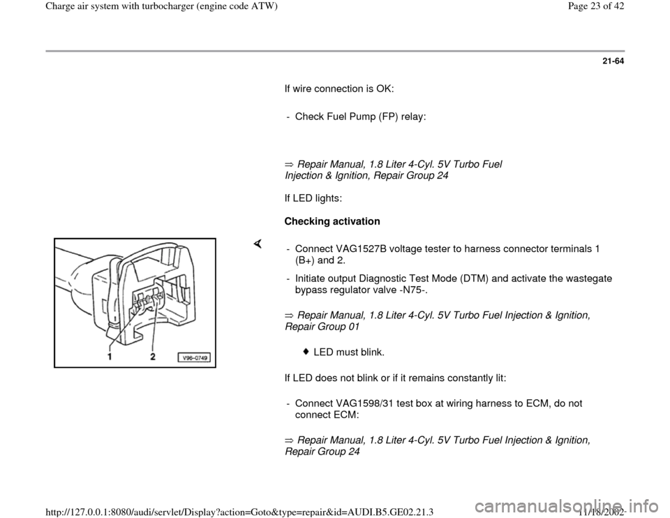
Repair Group 24 - Connect VAG1527B voltage tester to harness connector terminals 1
(B+) and 2.
- Initiate output Diagnostic Test Mode (DTM) and activate the wastegate
bypass regulator valve -N75-.
LED must blink.
- Connect VAG1598/31 test box at wiring harness to ECM, do not
connect ECM:
Pa
ge 23 of 42 Char
ge air s
ystem with turbochar
ger
(en
gine code ATW
)
11/18/2002 htt
p://127.0.0.1:8080/audi/servlet/Dis
play?action=Goto&t
yp
e=re
pair&id=AUDI.B5.GE02.21.3