lock AUDI A4 1997 B5 / 1.G AEB ATW Engines Exhaust System Components Workshop Manual
[x] Cancel search | Manufacturer: AUDI, Model Year: 1997, Model line: A4, Model: AUDI A4 1997 B5 / 1.GPages: 35, PDF Size: 0.46 MB
Page 1 of 35
26-1
Exhaust system components,
removing and installing
WARNING!
Do not re-use any fasteners that are worn or
deformed in normal use.
Some fasteners are designed to be used only
once, and are unreliable and may fail if used
a second time. This includes, but is not
limited to, nuts, bolts, washers, circlips and
cotter pins. Always follow the
recommendations in this manual-replace
these fasteners with new parts where
indicated, and any other time it is deemed
necessary by inspection.
Note:
Always replace gaskets and self-locking nuts.
After exhaust system repairs, make sure
exhaust system is not under stress and that it
has sufficient clearance from the bodywork. If
necessary, loosen double clamps and align
muffler and exhaust pipe so that sufficient
clearance is maintained to the bodywork and
the support rings are evenly loaded.
Pa
ge 1 of 35 Exhaust s
ystem com
ponents, removin
g and installin
g
11/18/2002 htt
p://127.0.0.1:8080/audi/servlet/Dis
play?action=Goto&t
yp
e=re
pair&id=AUDI.B5.GE02.26.1
Page 17 of 35
26-12
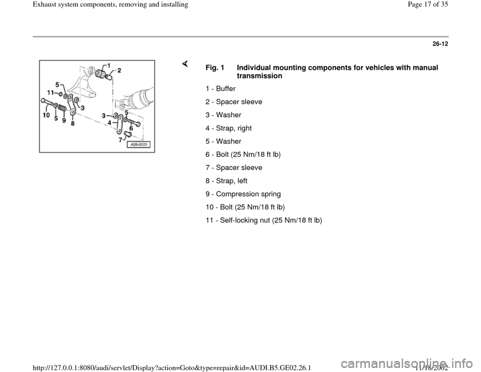
Fig. 1 Individual mounting components for vehicles with manual
transmission
1 - Buffer
2 - Spacer sleeve
3 - Washer
4 - Strap, right
5 - Washer
6 - Bolt (25 Nm/18 ft lb)
7 - Spacer sleeve
8 - Strap, left
9 - Compression spring
10 - Bolt (25 Nm/18 ft lb)
11 - Self-locking nut (25 Nm/18 ft lb)
Pa
ge 17 of 35 Exhaust s
ystem com
ponents, removin
g and installin
g
11/18/2002 htt
p://127.0.0.1:8080/audi/servlet/Dis
play?action=Goto&t
yp
e=re
pair&id=AUDI.B5.GE02.26.1
Page 18 of 35
26-13
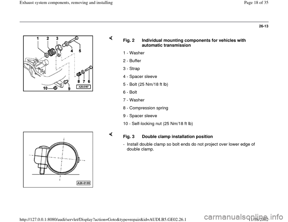
Fig. 2 Individual mounting components for vehicles with
automatic transmission
1 - Washer
2 - Buffer
3 - Strap
4 - Spacer sleeve
5 - Bolt (25 Nm/18 ft lb)
6 - Bolt
7 - Washer
8 - Compression spring
9 - Spacer sleeve
10 - Self-locking nut (25 Nm/18 ft lb)
Fig. 3 Double clamp installation position
- Install double clamp so bolt ends do not project over lower edge of
double clamp.
Pa
ge 18 of 35 Exhaust s
ystem com
ponents, removin
g and installin
g
11/18/2002 htt
p://127.0.0.1:8080/audi/servlet/Dis
play?action=Goto&t
yp
e=re
pair&id=AUDI.B5.GE02.26.1
Page 22 of 35
26-17
Exhaust manifold, removing and
installing
Removing
Note:
Replace gaskets and self-locking nuts.
Flexpipe in front exhaust pipe must not be bent
more than 10 , otherwise it may be damaged.
- Remove air guide duct between cowl and air
cleaner housing.
- Remove air cleaner housing cover.
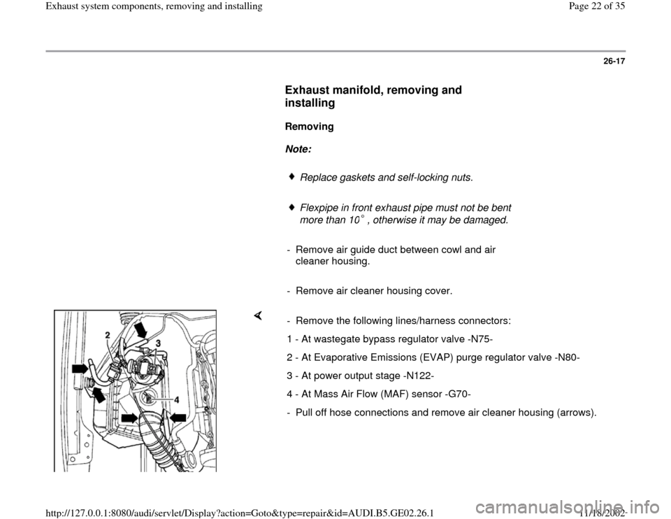
- Remove the following lines/harness connectors:
1 - At wastegate bypass regulator valve -N75-
2 - At Evaporative Emissions (EVAP) purge regulator valve -N80-
3 - At power output stage -N122-
4 - At Mass Air Flow (MAF) sensor -G70-
- Pull off hose connections and remove air cleaner housing (arrows).
Pa
ge 22 of 35 Exhaust s
ystem com
ponents, removin
g and installin
g
11/18/2002 htt
p://127.0.0.1:8080/audi/servlet/Dis
play?action=Goto&t
yp
e=re
pair&id=AUDI.B5.GE02.26.1
Page 25 of 35
26-20
Installing
Installation is the reverse of removal, noting the
following:
- Install in sequential order as follows:
Exhaust manifold to cylinder head
Turbocharger to exhaust manifold
Turbocharger bracket to cylinder block
Tightening torques
Component
Tightening
torques
Turbocharger bracket to
turbocharger (bolt and washer
assembly M8) 40 Nm (30 ft
lb)
Turbocharger bracket to cylinder
block 45 Nm (33 ft
lb)
Turbocharger to exhaust
manifold 35 Nm (26 ft
lb)
Exhaust manifold to cylinder
head 25 Nm (18 ft
lb)
Oil supply line to cylinder head 20 Nm (15 ft
Pa
ge 25 of 35 Exhaust s
ystem com
ponents, removin
g and installin
g
11/18/2002 htt
p://127.0.0.1:8080/audi/servlet/Dis
play?action=Goto&t
yp
e=re
pair&id=AUDI.B5.GE02.26.1
Page 27 of 35
26-21
Three Way Catalytic Converter (TWC),
removing and installing
Removing
Note:
Replace gaskets and self-locking nuts.
Flexpipe in front exhaust pipe must not be bent
more than 10 , otherwise it may be damaged.
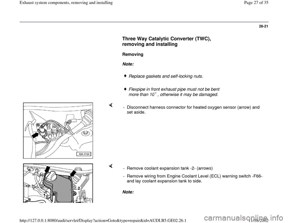
- Disconnect harness connector for heated oxygen sensor (arrow) and
set aside.
Note: - Remove coolant expansion tank -2- (arrows)
- Remove wiring from Engine Coolant Level (ECL) warning switch -F66-
and lay coolant expansion tank to side.
Pa
ge 27 of 35 Exhaust s
ystem com
ponents, removin
g and installin
g
11/18/2002 htt
p://127.0.0.1:8080/audi/servlet/Dis
play?action=Goto&t
yp
e=re
pair&id=AUDI.B5.GE02.26.1