display AUDI A4 1997 B5 / 1.G AFC Engine On Board Diagnostic Multiport Fuel Injection Workshop Manual
[x] Cancel search | Manufacturer: AUDI, Model Year: 1997, Model line: A4, Model: AUDI A4 1997 B5 / 1.GPages: 366, PDF Size: 1.21 MB
Page 218 of 366
01-158
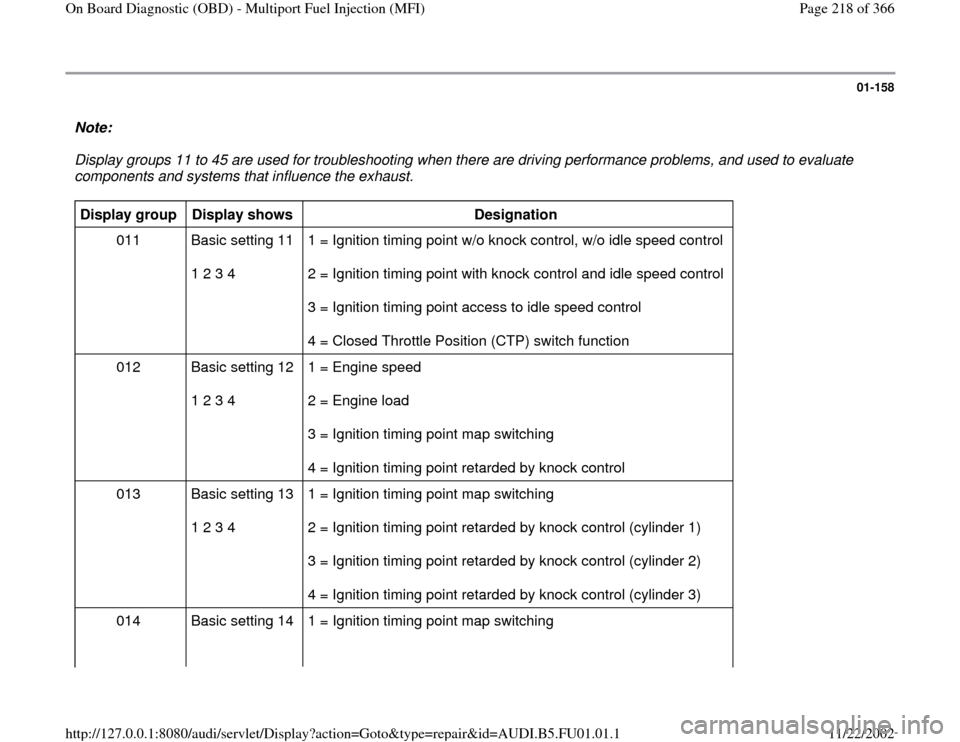
Note:
Display groups 11 to 45 are used for troubleshooting when there are driving performance problems, and used to evaluate
components and systems that influence the exhaust. Display group
Display shows
Designation
011 Basic setting 11
1 2 3 4 1 = Ignition timing point w/o knock control, w/o idle speed control
2 = Ignition timing point with knock control and idle speed control
3 = Ignition timing point access to idle speed control
4 = Closed Throttle Position (CTP) switch function
012 Basic setting 12
1 2 3 4 1 = Engine speed
2 = Engine load
3 = Ignition timing point map switching
4 = Ignition timing point retarded by knock control
013 Basic setting 13
1 2 3 4 1 = Ignition timing point map switching
2 = Ignition timing point retarded by knock control (cylinder 1)
3 = Ignition timing point retarded by knock control (cylinder 2)
4 = Ignition timing point retarded by knock control (cylinder 3)
014 Basic setting 14 1 = Ignition timing point map switching
Pa
ge 218 of 366 On Board Dia
gnostic
(OBD
) - Multi
port Fuel In
jection
(MFI
)
11/22/2002 htt
p://127.0.0.1:8080/audi/servlet/Dis
play?action=Goto&t
yp
e=re
pair&id=AUDI.B5.FU01.01.1
Page 220 of 366

01-159
Display group
Display shows
Designation
016 Basic setting 16
1 2 3 4 1 = Engine speed (RPM)
2 = Knock sensor signal (cylinder 4)
3 = Knock sensor signal (cylinder 5)
4 = Knock sensor signal (cylinder 6)
017
(vehicles with
EGR) Basic setting 17
1 2 3 4 1 = Timer 1
2 = Timer 2
3 = Engine load
4 = Exhaust gas recirculation temperature
018 Basic setting 18
1 2 3 4 1 = Specified internal duty cycle of Idle Air Control (IAC) valve -N71-
2 = Current draw by Idle Air Control (IAC) valve -N71-
3 = Power control from Idle Air Control (IAC) valve -N71-
4 = Engine Control Module (ECM) voltage supply
019 Basic setting 19
1 2 3 4 1 = Engine power
2 = Intake air volume
3 = Vehicle speed
4 = Fuel injection time
Pa
ge 220 of 366 On Board Dia
gnostic
(OBD
) - Multi
port Fuel In
jection
(MFI
)
11/22/2002 htt
p://127.0.0.1:8080/audi/servlet/Dis
play?action=Goto&t
yp
e=re
pair&id=AUDI.B5.FU01.01.1
Page 222 of 366
01-160
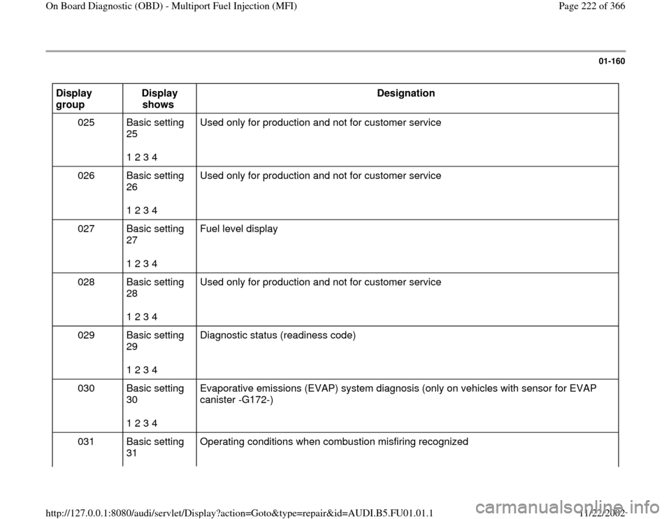
Display
group Display
shows Designation
025 Basic setting
25
1 2 3 4 Used only for production and not for customer service
026 Basic setting
26
1 2 3 4 Used only for production and not for customer service
027 Basic setting
27
1 2 3 4 Fuel level display
028 Basic setting
28
1 2 3 4 Used only for production and not for customer service
029 Basic setting
29
1 2 3 4 Diagnostic status (readiness code)
030 Basic setting
30
1 2 3 4 Evaporative emissions (EVAP) system diagnosis (only on vehicles with sensor for EVAP
canister -G172-)
031 Basic setting
31 Operating conditions when combustion misfiring recognized
Pa
ge 222 of 366 On Board Dia
gnostic
(OBD
) - Multi
port Fuel In
jection
(MFI
)
11/22/2002 htt
p://127.0.0.1:8080/audi/servlet/Dis
play?action=Goto&t
yp
e=re
pair&id=AUDI.B5.FU01.01.1
Page 224 of 366
01-161
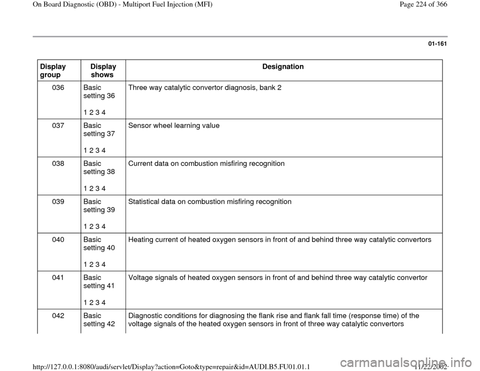
Display
group Display
shows Designation
036 Basic
setting 36
1 2 3 4 Three way catalytic convertor diagnosis, bank 2
037 Basic
setting 37
1 2 3 4 Sensor wheel learning value
038 Basic
setting 38
1 2 3 4 Current data on combustion misfiring recognition
039 Basic
setting 39
1 2 3 4 Statistical data on combustion misfiring recognition
040 Basic
setting 40
1 2 3 4 Heating current of heated oxygen sensors in front of and behind three way catalytic convertors
041 Basic
setting 41
1 2 3 4 Voltage signals of heated oxygen sensors in front of and behind three way catalytic convertor
042 Basic
setting 42 Diagnostic conditions for diagnosing the flank rise and flank fall time (response time) of the
voltage signals of the heated oxygen sensors in front of three way catalytic convertors
Pa
ge 224 of 366 On Board Dia
gnostic
(OBD
) - Multi
port Fuel In
jection
(MFI
)
11/22/2002 htt
p://127.0.0.1:8080/audi/servlet/Dis
play?action=Goto&t
yp
e=re
pair&id=AUDI.B5.FU01.01.1
Page 226 of 366

01-162
099 Basic setting 99
1 2 3 4 1 = Momentary engine speed
2 = Momentary engine load
3 = Coolant temperature
4 = Oxygen sensor control OFF/ON Note:
Display group 99 can switch the oxygen sensor control on or off.
Pa
ge 226 of 366 On Board Dia
gnostic
(OBD
) - Multi
port Fuel In
jection
(MFI
)
11/22/2002 htt
p://127.0.0.1:8080/audi/servlet/Dis
play?action=Goto&t
yp
e=re
pair&id=AUDI.B5.FU01.01.1
Page 227 of 366
01-163
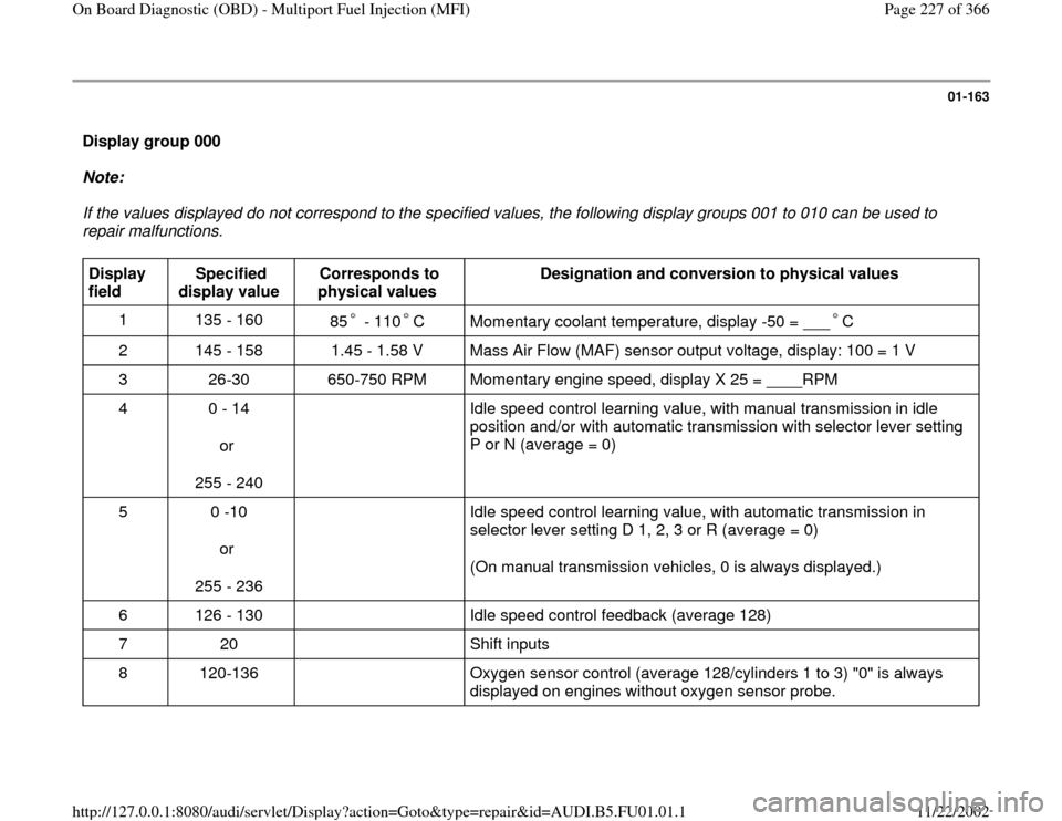
Display group 000
Note:
If the values displayed do not correspond to the specified values, the following display groups 001 to 010 can be used to
repair malfunctions. Display
field Specified
display value Corresponds to
physical values Designation and conversion to physical values
1 135 - 160
85 - 110 C
Momentary coolant temperature, display -50 = ___ C
2 145 - 158 1.45 - 1.58 V Mass Air Flow (MAF) sensor output voltage, display: 100 = 1 V
3 26-30 650-750 RPM Momentary engine speed, display X 25 = ____RPM
4 0 - 14
or
255 - 240 Idle speed control learning value, with manual transmission in idle
position and/or with automatic transmission with selector lever setting
P or N (average = 0)
5 0 -10
or
255 - 236 Idle speed control learning value, with automatic transmission in
selector lever setting D 1, 2, 3 or R (average = 0)
(On manual transmission vehicles, 0 is always displayed.)
6 126 - 130 Idle speed control feedback (average 128)
7 20 Shift inputs
8 120-136 Oxygen sensor control (average 128/cylinders 1 to 3) "0" is always
displayed on engines without oxygen sensor probe.
Pa
ge 227 of 366 On Board Dia
gnostic
(OBD
) - Multi
port Fuel In
jection
(MFI
)
11/22/2002 htt
p://127.0.0.1:8080/audi/servlet/Dis
play?action=Goto&t
yp
e=re
pair&id=AUDI.B5.FU01.01.1
Page 228 of 366

Note on display field 8:
Deviations in display field 8 should only be considered after the oxygen sensor learning process at idle has been completed
display field 9.
Pa
ge 228 of 366 On Board Dia
gnostic
(OBD
) - Multi
port Fuel In
jection
(MFI
)
11/22/2002 htt
p://127.0.0.1:8080/audi/servlet/Dis
play?action=Goto&t
yp
e=re
pair&id=AUDI.B5.FU01.01.1
Page 229 of 366
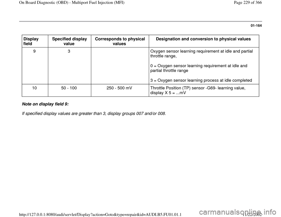
01-164
Display
field Specified display
value Corresponds to physical
values Designation and conversion to physical values
9 3 Oxygen sensor learning requirement at idle and partial
throttle range,
0 = Oxygen sensor learning requirement at idle and
partial throttle range
3 = Oxygen sensor learning process at idle completed
10 50 - 100 250 - 500 mV Throttle Position (TP) sensor -G69- learning value,
display X 5 = ...mV Note on display field 9:
If specified display values are greater than 3, display groups 007 and/or 008.
Pa
ge 229 of 366 On Board Dia
gnostic
(OBD
) - Multi
port Fuel In
jection
(MFI
)
11/22/2002 htt
p://127.0.0.1:8080/audi/servlet/Dis
play?action=Goto&t
yp
e=re
pair&id=AUDI.B5.FU01.01.1
Page 230 of 366
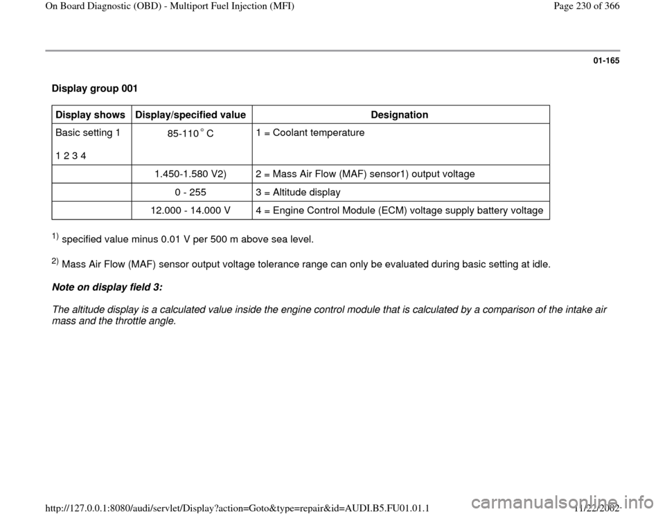
01-165
Display group 001 Display shows
Display/specified value
Designation
Basic setting 1
1 2 3 4 85-110 C
1 = Coolant temperature
1.450-1.580 V2) 2 = Mass Air Flow (MAF) sensor1) output voltage
0 - 255 3 = Altitude display
12.000 - 14.000 V 4 = Engine Control Module (ECM) voltage supply battery voltage
1) specified value minus 0.01 V per 500 m above sea level. 2) Mass Air Flow (MAF) sensor output voltage tolerance range can only be evaluated during basic setting at idle.
Note on display field 3:
The altitude display is a calculated value inside the engine control module that is calculated by a comparison of the intake air
mass and the throttle angle.
Pa
ge 230 of 366 On Board Dia
gnostic
(OBD
) - Multi
port Fuel In
jection
(MFI
)
11/22/2002 htt
p://127.0.0.1:8080/audi/servlet/Dis
play?action=Goto&t
yp
e=re
pair&id=AUDI.B5.FU01.01.1
Page 231 of 366
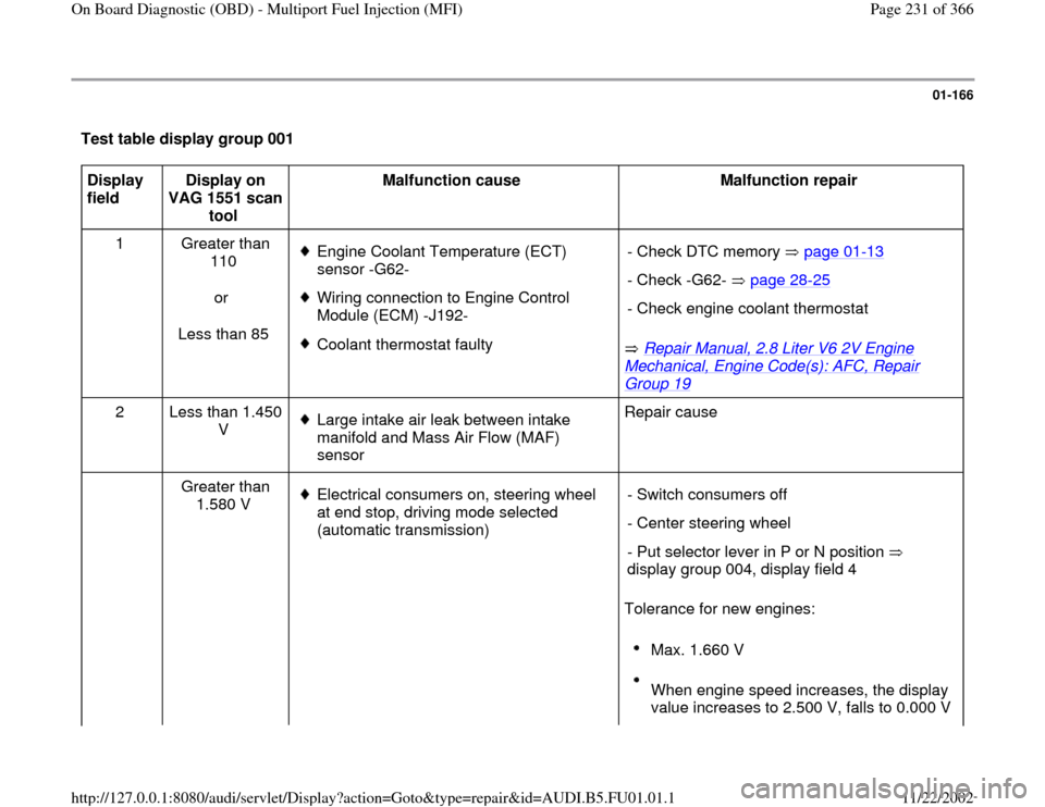
01-166
Test table display group 001 Display
field Display on
VAG 1551 scan
tool Malfunction cause
Malfunction repair
1 Greater than
110
or
Less than 85
Engine Coolant Temperature (ECT)
sensor -G62-
Wiring connection to Engine Control
Module (ECM) -J192-
Coolant thermostat faulty
Repair Manual, 2.8 Liter V6 2V Engine
Mechanical, Engine Code(s): AFC, Repair Group 19
- Check DTC memory page 01
-13
- Check -G62- page 28
-25
- Check engine coolant thermostat
2 Less than 1.450
V
Large intake air leak between intake
manifold and Mass Air Flow (MAF)
sensor Repair cause
Greater than
1.580 V Electrical consumers on, steering wheel
at end stop, driving mode selected
(automatic transmission)
Tolerance for new engines: - Switch consumers off
- Center steering wheel
- Put selector lever in P or N position
display group 004, display field 4
Max. 1.660 V
When engine speed increases, the display
value increases to 2.500 V, falls to 0.000 V
Pa
ge 231 of 366 On Board Dia
gnostic
(OBD
) - Multi
port Fuel In
jection
(MFI
)
11/22/2002 htt
p://127.0.0.1:8080/audi/servlet/Dis
play?action=Goto&t
yp
e=re
pair&id=AUDI.B5.FU01.01.1