transmission AUDI A4 1997 B5 / 1.G AFC Engine On Board Diagnostic Multiport Fuel Injection Owner's Manual
[x] Cancel search | Manufacturer: AUDI, Model Year: 1997, Model line: A4, Model: AUDI A4 1997 B5 / 1.GPages: 366, PDF Size: 1.21 MB
Page 242 of 366

01-173
Display group 004 Display
shows Display/specified
value Designation
Basic
setting 4
1 2 3 4 0 2
1 = Idle air control valve at idle
HS: +14 to -16
or
AT: +10 to -20 2 = Idle speed control learning value in manual transmission (HS) at idle setting and/or
with automatic transmission (AT) in selector lever setting P or N
Variation permitted for new engines:
HS: +20 to -16AT: +16 to -20)
HS: 0
or
AT: +10 to -20 3 = Idle speed control learning value in automatic transmission (AT) in selector lever
setting D, 1, 2, 3 or R. (0 is always displayed in vehicles with manual transmission.)
001 10 4 = Shift inputs at idle:
0 off 1 on
Notes:
Values in display fields 2 and/or 3 can only be evaluated with idle air control valve is within tolerance at idle (display value
1). If the idle air control valve is not within tolerance after 1 minute waiting time, no learning takes place in display fields 2
and/or 3 .
Pa
ge 242 of 366 On Board Dia
gnostic
(OBD
) - Multi
port Fuel In
jection
(MFI
)
11/22/2002 htt
p://127.0.0.1:8080/audi/servlet/Dis
play?action=Goto&t
yp
e=re
pair&id=AUDI.B5.FU01.01.1
Page 244 of 366
01-174
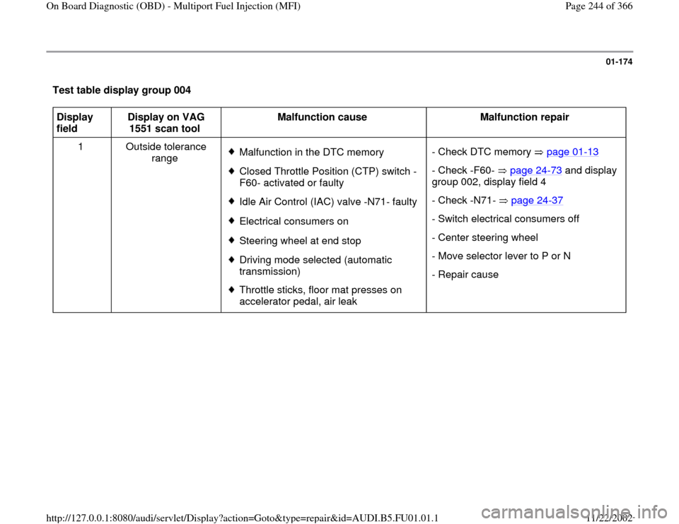
Test table display group 004 Display
field Display on VAG
1551 scan tool Malfunction cause
Malfunction repair
1 Outside tolerance
range
Malfunction in the DTC memoryClosed Throttle Position (CTP) switch -
F60- activated or faulty Idle Air Control (IAC) valve -N71- faulty Electrical consumers onSteering wheel at end stop Driving mode selected (automatic
transmission) Throttle sticks, floor mat presses on
accelerator pedal, air leak - Check DTC memory page 01
-13
- Check -F60- page 24
-73
and display
group 002, display field 4
- Check -N71- page 24
-37
- Switch electrical consumers off
- Center steering wheel
- Move selector lever to P or N
- Repair cause
Pa
ge 244 of 366 On Board Dia
gnostic
(OBD
) - Multi
port Fuel In
jection
(MFI
)
11/22/2002 htt
p://127.0.0.1:8080/audi/servlet/Dis
play?action=Goto&t
yp
e=re
pair&id=AUDI.B5.FU01.01.1
Page 245 of 366
01-175
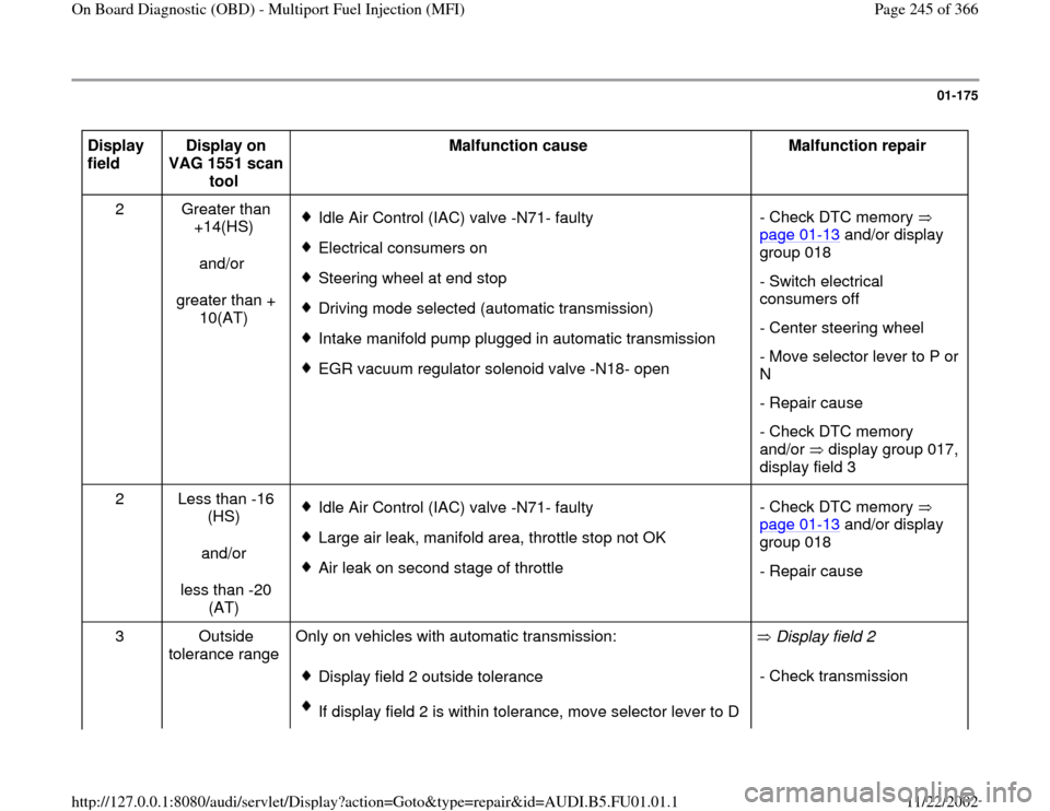
Display
field Display on
VAG 1551 scan
tool Malfunction cause
Malfunction repair
2 Greater than
+14(HS)
and/or
greater than +
10(AT)
Idle Air Control (IAC) valve -N71- faulty
Electrical consumers on
Steering wheel at end stop
Driving mode selected (automatic transmission)
Intake manifold pump plugged in automatic transmission
EGR vacuum regulator solenoid valve -N18- open- Check DTC memory
page 01
-13
and/or display
group 018
- Switch electrical
consumers off
- Center steering wheel
- Move selector lever to P or
N
- Repair cause
- Check DTC memory
and/or display group 017,
display field 3
2 Less than -16
(HS)
and/or
less than -20
(AT)
Idle Air Control (IAC) valve -N71- faulty
Large air leak, manifold area, throttle stop not OK
Air leak on second stage of throttle - Check DTC memory
page 01
-13
and/or display
group 018
- Repair cause
3 Outside
tolerance range Only on vehicles with automatic transmission:
Display field 2 outside tolerance
If display field 2 is within tolerance, move selector lever to D Display field 2
- Check transmission
Pa
ge 245 of 366 On Board Dia
gnostic
(OBD
) - Multi
port Fuel In
jection
(MFI
)
11/22/2002 htt
p://127.0.0.1:8080/audi/servlet/Dis
play?action=Goto&t
yp
e=re
pair&id=AUDI.B5.FU01.01.1
Page 246 of 366

and observe idle for approx. 1 min.; if display field 3 stays
outside tolerance, the transmission is hard to move
Pa
ge 246 of 366 On Board Dia
gnostic
(OBD
) - Multi
port Fuel In
jection
(MFI
)
11/22/2002 htt
p://127.0.0.1:8080/audi/servlet/Dis
play?action=Goto&t
yp
e=re
pair&id=AUDI.B5.FU01.01.1
Page 247 of 366
01-176
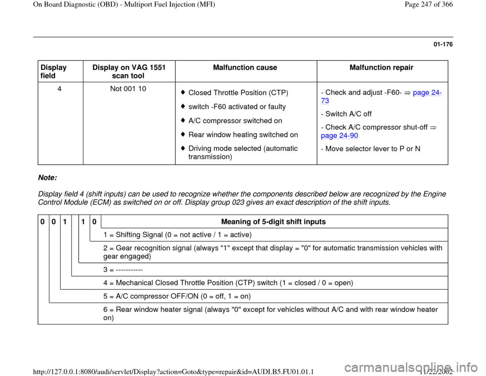
Display
field Display on VAG 1551
scan tool Malfunction cause
Malfunction repair
4 Not 001 10
Closed Throttle Position (CTP) switch -F60 activated or faulty A/C compressor switched on Rear window heating switched on Driving mode selected (automatic
transmission) - Check and adjust -F60- page 24
-
73
- Switch A/C off
- Check A/C compressor shut-off
page 24
-90
- Move selector lever to P or N
Note:
Display field 4 (shift inputs) can be used to recognize whether the components described below are recognized by the Engine
Control Module (ECM) as switched on or off. Display group 023 gives an exact description of the shift inputs. 0
0
1
1
0
Meaning of 5-digit shift inputs
1 = Shifting Signal (0 = not active / 1 = active)
2 = Gear recognition signal (always "1" except that display = "0" for automatic transmission vehicles with
gear engaged)
3 = -----------
4 = Mechanical Closed Throttle Position (CTP) switch (1 = closed / 0 = open)
5 = A/C compressor OFF/ON (0 = off, 1 = on)
6 = Rear window heater signal (always "0" except for vehicles without A/C and with rear window heater
on)
Pa
ge 247 of 366 On Board Dia
gnostic
(OBD
) - Multi
port Fuel In
jection
(MFI
)
11/22/2002 htt
p://127.0.0.1:8080/audi/servlet/Dis
play?action=Goto&t
yp
e=re
pair&id=AUDI.B5.FU01.01.1
Page 289 of 366
01-205
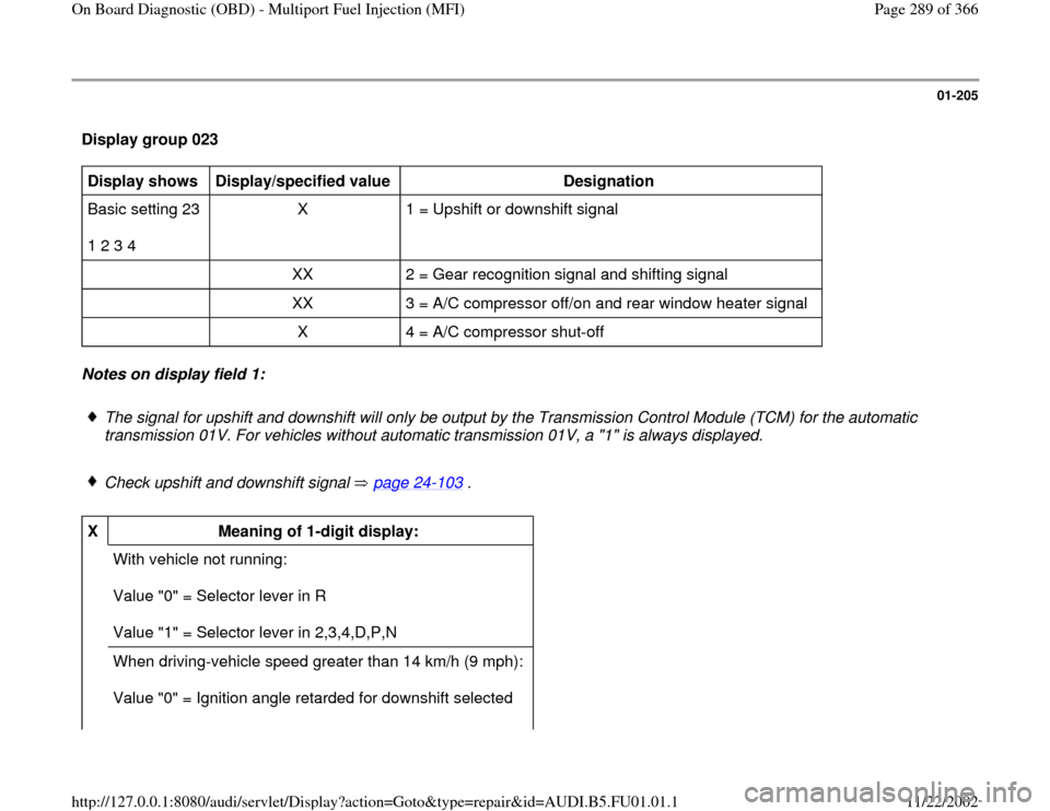
Display group 023 Display shows
Display/specified value
Designation
Basic setting 23
1 2 3 4 X 1 = Upshift or downshift signal
XX 2 = Gear recognition signal and shifting signal
XX 3 = A/C compressor off/on and rear window heater signal
X 4 = A/C compressor shut-off Notes on display field 1:
The signal for upshift and downshift will only be output by the Transmission Control Module (TCM) for the automatic
transmission 01V. For vehicles without automatic transmission 01V, a "1" is always displayed.
Check upshift and downshift signal page 24
-103
.
X
Meaning of 1-digit display:
With vehicle not running:
Value "0" = Selector lever in R
Value "1" = Selector lever in 2,3,4,D,P,N
When driving-vehicle speed greater than 14 km/h (9 mph):
Value "0" = Ignition angle retarded for downshift selected
Pa
ge 289 of 366 On Board Dia
gnostic
(OBD
) - Multi
port Fuel In
jection
(MFI
)
11/22/2002 htt
p://127.0.0.1:8080/audi/servlet/Dis
play?action=Goto&t
yp
e=re
pair&id=AUDI.B5.FU01.01.1
Page 291 of 366
01-206
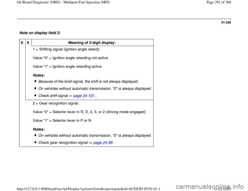
Note on display field 2: X
X
Meaning of 2-digit display:
1 = Shifting signal (ignition angle retard):
Value "0" = Ignition angle retarding not active
Value "1" = Ignition angle retarding active
Notes:
Because of the brief signal, the shift is not always displayed.
On vehicles without automatic transmission, "0" is always displayed.
Check shift signal page 24
-101
.
2 = Gear recognition signal:
Value "0" = Selector lever in R, D, 4, 3, or 2 (driving mode engaged)
Value "1" = Selector lever in P or N
Notes:
On vehicles without automatic transmission, "0" is always displayed.
Check gear recognition signal page 24
-99
.
Pa
ge 291 of 366 On Board Dia
gnostic
(OBD
) - Multi
port Fuel In
jection
(MFI
)
11/22/2002 htt
p://127.0.0.1:8080/audi/servlet/Dis
play?action=Goto&t
yp
e=re
pair&id=AUDI.B5.FU01.01.1
Page 292 of 366
01-207
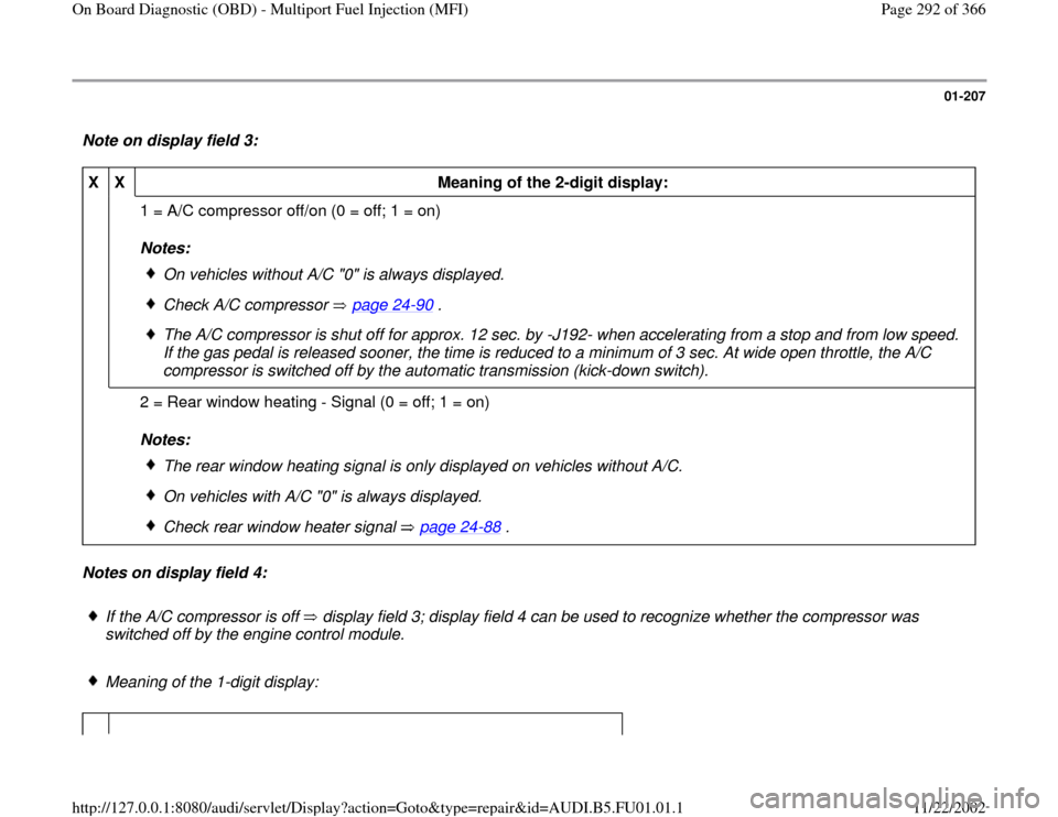
Note on display field 3: X
X
Meaning of the 2-digit display:
1 = A/C compressor off/on (0 = off; 1 = on)
Notes:
On vehicles without A/C "0" is always displayed.
Check A/C compressor page 24
-90
.
The A/C compressor is shut off for approx. 12 sec. by -J192- when accelerating from a stop and from low speed.
If the gas pedal is released sooner, the time is reduced to a minimum of 3 sec. At wide open throttle, the A/C
compressor is switched off by the automatic transmission (kick-down switch).
2 = Rear window heating - Signal (0 = off; 1 = on)
Notes:
The rear window heating signal is only displayed on vehicles without A/C.
On vehicles with A/C "0" is always displayed.
Check rear window heater signal page 24
-88
.
Notes on display field 4:
If the A/C compressor is off display field 3; display field 4 can be used to recognize whether the compressor was
switched off by the engine control module. Meaning of the 1-digit display:
Pa
ge 292 of 366 On Board Dia
gnostic
(OBD
) - Multi
port Fuel In
jection
(MFI
)
11/22/2002 htt
p://127.0.0.1:8080/audi/servlet/Dis
play?action=Goto&t
yp
e=re
pair&id=AUDI.B5.FU01.01.1
Page 296 of 366
01-209
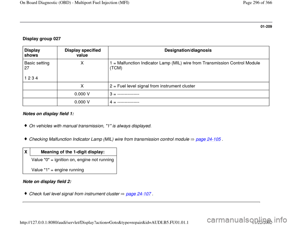
Display group 027 Display
shows Display specified
value Designation/diagnosis
Basic setting
27
1 2 3 4 X 1 = Malfunction Indicator Lamp (MIL) wire from Transmission Control Module
(TCM)
X 2 = Fuel level signal from instrument cluster
0.000 V 3 = ---------------
0.000 V 4 = --------------- Notes on display field 1:
On vehicles with manual transmission, "1" is always displayed.
Checking Malfunction Indicator Lamp (MIL) wire from transmission control module page 24
-105
.
X
Meaning of the 1-digit display:
Value "0" = ignition on, engine not running
Value "1" = engine running Note on display field 2:
Check fuel level signal from instrument cluster page 24
-107
.
Pa
ge 296 of 366 On Board Dia
gnostic
(OBD
) - Multi
port Fuel In
jection
(MFI
)
11/22/2002 htt
p://127.0.0.1:8080/audi/servlet/Dis
play?action=Goto&t
yp
e=re
pair&id=AUDI.B5.FU01.01.1
Page 299 of 366
01-211
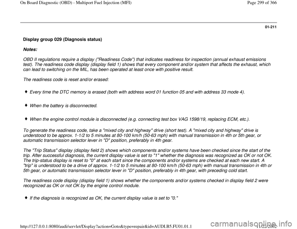
Display group 029 (Diagnosis status)
Notes:
OBD II regulations require a display ("Readiness Code") that indicates readiness for inspection (annual exhaust emissions
test). The readiness code display (display field 1) shows that every component and/or system that affects the exhaust, which
can lead to switching on the MIL, has been operated at least once with positive result.
The readiness code is reset and/or erased:
Every time the DTC memory is erased (both with address word 01 function 05 and with address 33 mode 4).
When the battery is disconnected.
When the engine control module is disconnected (e.g. connecting test box VAG 1598/19, replacing ECM, etc.).
To generate the readiness code, take a "mixed city and highway" drive (short test). A "mixed city and highway" drive is
understood to be approx. 1-1/2 to 5 minutes at 80-100 km/h (50-63 mph) with manual transmission in 4th or 5th gear, or
automatic transmission selector lever in "D" position, preferably in 4th gear.
The "Trip Status" display (display field 2) shows which components and/or systems have been checked since the start of the
trip. After successful diagnosis, the current display value is set to "1" whether the diagnosis was recognized as OK or not OK.
The trip-status display is reset to "0" at each start since the components and/or systems are checked at each new start. A
"trip" is understood to be a drive of approx. 1-1/2 to 5 minutes at 80-100 km/h (50-63 mph) with manual transmission in 4th or
5th gear, or automatic transmission selector lever in "D" position, preferably in 4th gear, with preceding cold start.
The readiness code display (display field 1) shows whether the components and/or systems checked in display field 2 were
recognized as OK or not OK by the engine control module.
If the diagnosis is recognized as OK, the current display value is set to "0."
Pa
ge 299 of 366 On Board Dia
gnostic
(OBD
) - Multi
port Fuel In
jection
(MFI
)
11/22/2002 htt
p://127.0.0.1:8080/audi/servlet/Dis
play?action=Goto&t
yp
e=re
pair&id=AUDI.B5.FU01.01.1