wiring diagram AUDI A4 1997 B5 / 1.G AFC Engine On Board Diagnostic Multiport Fuel Injection Workshop Manual
[x] Cancel search | Manufacturer: AUDI, Model Year: 1997, Model line: A4, Model: AUDI A4 1997 B5 / 1.GPages: 366, PDF Size: 1.21 MB
Page 7 of 366
01-4
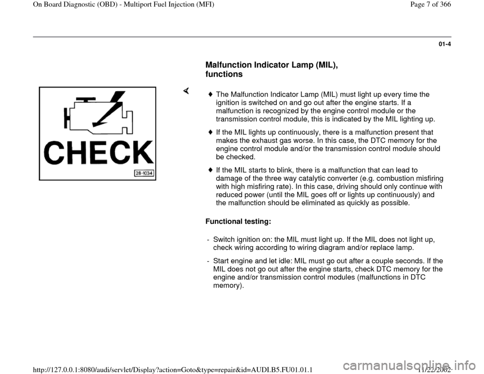
Malfunction Indicator Lamp (MIL),
functions
Functional testing:
The Malfunction Indicator Lamp (MIL) must light up every time the
ignition is switched on and go out after the engine starts. If a
malfunction is recognized by the engine control module or the
transmission control module, this is indicated by the MIL lighting up. If the MIL lights up continuously, there is a malfunction present that
makes the exhaust gas worse. In this case, the DTC memory for the
engine control module and/or the transmission control module should
be checked. If the MIL starts to blink, there is a malfunction that can lead to
damage of the three way catalytic converter (e.g. combustion misfiring
with high misfiring rate). In this case, driving should only continue with
reduced power (until the MIL goes off or lights up continuously) and
the malfunction should be eliminated as quickly as possible.
- Switch ignition on: the MIL must light up. If the MIL does not light up,
check wiring according to wiring diagram and/or replace lamp.
- Start engine and let idle: MIL must go out after a couple seconds. If the
MIL does not go out after the engine starts, check DTC memory for the
engine and/or transmission control modules (malfunctions in DTC
memory).
Pa
ge 7 of 366 On Board Dia
gnostic
(OBD
) - Multi
port Fuel In
jection
(MFI
)
11/22/2002 htt
p://127.0.0.1:8080/audi/servlet/Dis
play?action=Goto&t
yp
e=re
pair&id=AUDI.B5.FU01.01.1
Page 13 of 366
Electrical Wiring Diagrams, Troubleshooting & Component Locations Additional operating instructions can be obtained by using the VAG
1551 scan tool HELP button. The button is used to advance to the next program step.
Pa
ge 13 of 366 On Board Dia
gnostic
(OBD
) - Multi
port Fuel In
jection
(MFI
)
11/22/2002 htt
p://127.0.0.1:8080/audi/servlet/Dis
play?action=Goto&t
yp
e=re
pair&id=AUDI.B5.FU01.01.1
Page 16 of 366
01-10
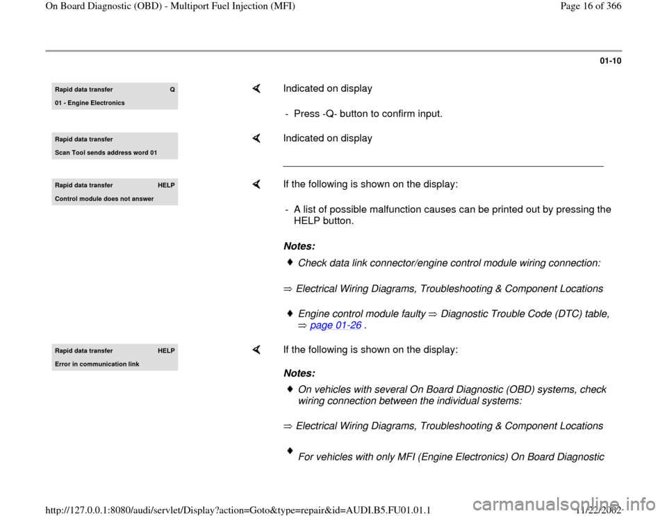
Rapid data transfer
Q
01 - Engine Electronics
Indicated on display
- Press -Q- button to confirm input.
Rapid data transfer Scan Tool sends address word 01
Indicated on display
_________________________________________________________
Rapid data transfer
HELP
Control module does not answer
If the following is shown on the display:
Notes:
Electrical Wiring Diagrams, Troubleshooting & Component Locations - A list of possible malfunction causes can be printed out by pressing the
HELP button.
Check data link connector/engine control module wiring connection:Engine control module faulty Diagnostic Trouble Code (DTC) table,
page 01
-26
.
Rapid data transfer
HELP
Error in communication link
If the following is shown on the display:
Notes:
Electrical Wiring Diagrams, Troubleshooting & Component Locations
On vehicles with several On Board Diagnostic (OBD) systems, check
wiring connection between the individual systems: For vehicles with only MFI (Engine Electronics) On Board Diagnostic
Pa
ge 16 of 366 On Board Dia
gnostic
(OBD
) - Multi
port Fuel In
jection
(MFI
)
11/22/2002 htt
p://127.0.0.1:8080/audi/servlet/Dis
play?action=Goto&t
yp
e=re
pair&id=AUDI.B5.FU01.01.1
Page 18 of 366
01-11
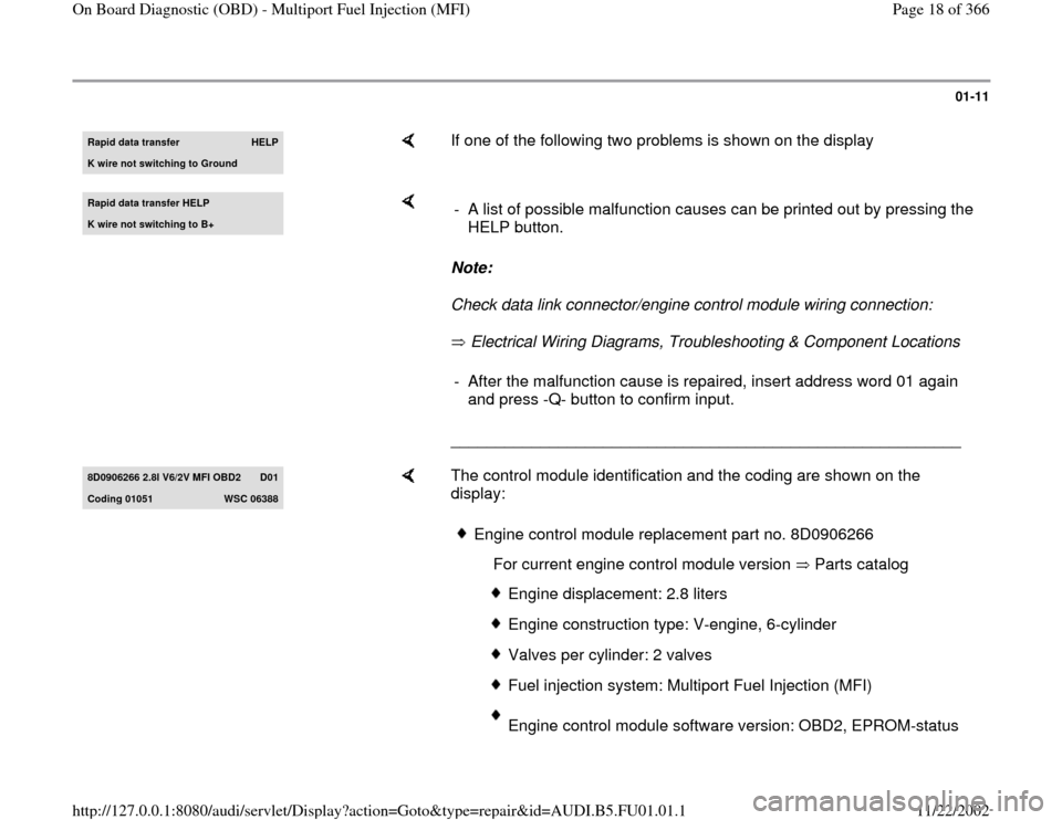
Rapid data transfer
HELP
K wire not switching to Ground
If one of the following two problems is shown on the display
Rapid data transfer HELPK wire not switching to B+
Note:
Check data link connector/engine control module wiring connection:
Electrical Wiring Diagrams, Troubleshooting & Component Locations
_________________________________________________________ - A list of possible malfunction causes can be printed out by pressing the
HELP button. - After the malfunction cause is repaired, insert address word 01 again
and press -Q- button to confirm input.
8D0906266 2.8l V6/2V MFI OBD2
D01
Codin
g 01051
WSC 06388
The control module identification and the coding are shown on the
display:
Engine control module replacement part no. 8D0906266
For current engine control module version Parts catalog
Engine displacement: 2.8 liters Engine construction type: V-engine, 6-cylinderValves per cylinder: 2 valvesFuel injection system: Multiport Fuel Injection (MFI)Engine control module software version: OBD2, EPROM-status
Pa
ge 18 of 366 On Board Dia
gnostic
(OBD
) - Multi
port Fuel In
jection
(MFI
)
11/22/2002 htt
p://127.0.0.1:8080/audi/servlet/Dis
play?action=Goto&t
yp
e=re
pair&id=AUDI.B5.FU01.01.1
Page 38 of 366
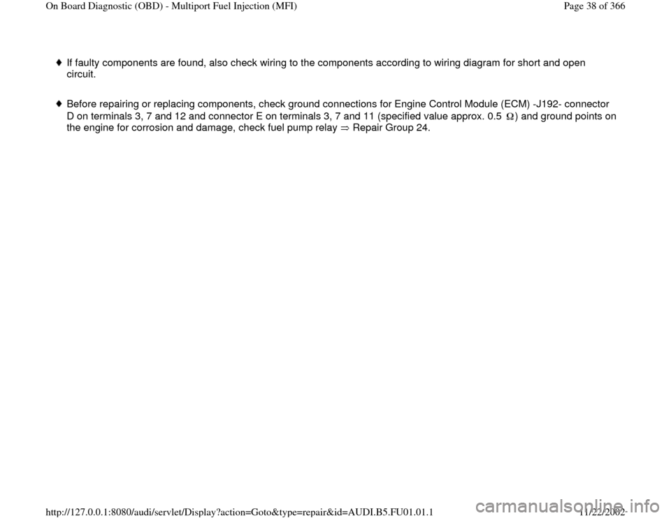
If faulty components are found, also check wiring to the components according to wiring diagram for short and open
circuit.
Before repairing or replacing components, check ground connections for Engine Control Module (ECM) -J192- connector
D on terminals 3, 7 and 12 and connector E on terminals 3, 7 and 11 (specified value approx. 0.5 ) and ground points on
the engine for corrosion and damage, check fuel pump relay Repair Group 24.
Pa
ge 38 of 366 On Board Dia
gnostic
(OBD
) - Multi
port Fuel In
jection
(MFI
)
11/22/2002 htt
p://127.0.0.1:8080/audi/servlet/Dis
play?action=Goto&t
yp
e=re
pair&id=AUDI.B5.FU01.01.1
Page 235 of 366
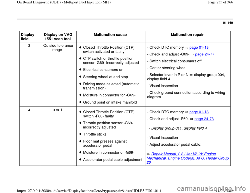
01-169
Display
field Display on VAG
1551 scan tool Malfunction cause
Malfunction repair
3 Outside tolerance
range
Closed Throttle Position (CTP)
switch activated or faulty CTP switch or throttle position
sensor -G69- incorrectly adjusted Electrical consumers onSteering wheel at end stopDriving mode selected (automatic
transmission) Moisture in connector for -G69-Ground point on intake manifold - Check DTC memory page 01
-13
- Check and adjust -G69- page 24
-77
- Switch electrical consumers off
- Center steering wheel
- Selector lever in P or N display group 004,
display field 4 - Visual inspection
- Check ground connection according to wiring
diagram
4 0 or 1
Closed Throttle Position (CTP)
switch -F60- faulty Throttle position sensor -G69-
incorrectly adjusted Throttle sticks Floor mat presses against
accelerator pedal Moisture in connector of -G69-Accelerator pedal cable adjustment Display group 011, display field 4
Repair Manual, 2.8 Liter V6 2V Engine
Mechanical, Engine Code(s): AFC, Repair Group 20
- Check DTC memory page 01
-13
- Check and adjust -F60- page 24
-73
- Visual inspection
- Adjust accelerator pedal cable:
Pa
ge 235 of 366 On Board Dia
gnostic
(OBD
) - Multi
port Fuel In
jection
(MFI
)
11/22/2002 htt
p://127.0.0.1:8080/audi/servlet/Dis
play?action=Goto&t
yp
e=re
pair&id=AUDI.B5.FU01.01.1
Page 240 of 366
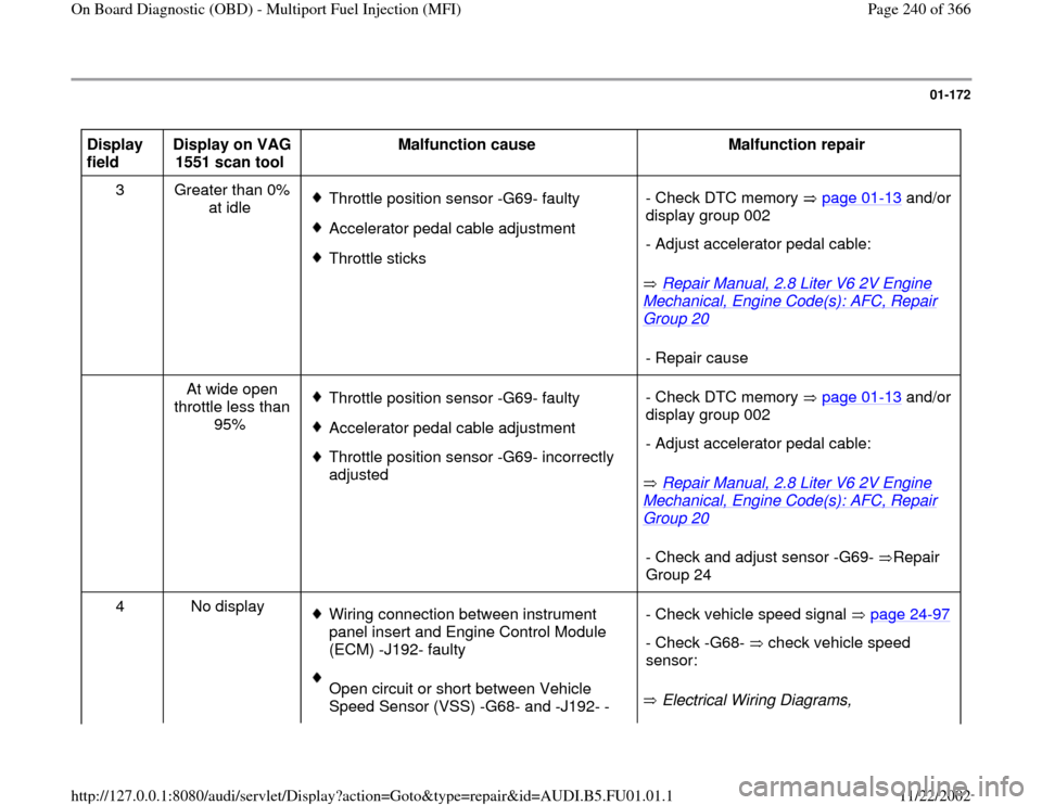
01-172
Display
field Display on VAG
1551 scan tool Malfunction cause
Malfunction repair
3 Greater than 0%
at idle
Throttle position sensor -G69- faultyAccelerator pedal cable adjustmentThrottle sticks
Repair Manual, 2.8 Liter V6 2V Engine
Mechanical, Engine Code(s): AFC, Repair Group 20
- Check DTC memory page 01
-13
and/or
display group 002
- Adjust accelerator pedal cable:- Repair cause
At wide open
throttle less than
95%
Throttle position sensor -G69- faultyAccelerator pedal cable adjustment Throttle position sensor -G69- incorrectly
adjusted
Repair Manual, 2.8 Liter V6 2V Engine
Mechanical, Engine Code(s): AFC, Repair Group 20
- Check DTC memory page 01
-13
and/or
display group 002
- Adjust accelerator pedal cable:- Check and adjust sensor -G69- Repair
Group 24
4 No display
Wiring connection between instrument
panel insert and Engine Control Module
(ECM) -J192- faulty Open circuit or short between Vehicle
Speed Sensor (VSS) -G68- and -J192- - Electrical Wiring Diagrams, - Check vehicle speed signal page 24
-97
- Check -G68- check vehicle speed
sensor:
Pa
ge 240 of 366 On Board Dia
gnostic
(OBD
) - Multi
port Fuel In
jection
(MFI
)
11/22/2002 htt
p://127.0.0.1:8080/audi/servlet/Dis
play?action=Goto&t
yp
e=re
pair&id=AUDI.B5.FU01.01.1
Page 241 of 366
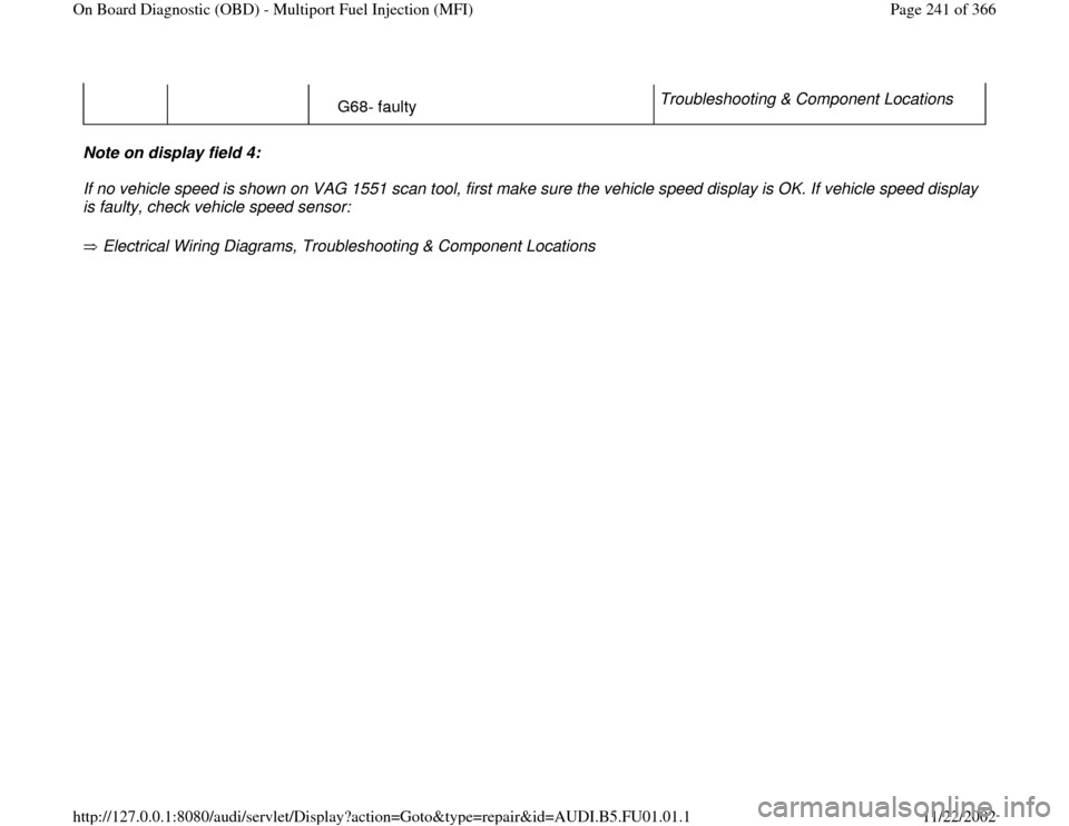
G68- faulty Troubleshooting & Component Locations
Note on display field 4:
If no vehicle speed is shown on VAG 1551 scan tool, first make sure the vehicle speed display is OK. If vehicle speed display
is faulty, check vehicle speed sensor:
Electrical Wiring Diagrams, Troubleshooting & Component Locations
Pa
ge 241 of 366 On Board Dia
gnostic
(OBD
) - Multi
port Fuel In
jection
(MFI
)
11/22/2002 htt
p://127.0.0.1:8080/audi/servlet/Dis
play?action=Goto&t
yp
e=re
pair&id=AUDI.B5.FU01.01.1