catalytic converter AUDI A4 1997 B5 / 1.G APB Engine Oxygen Sensor Control Checking User Guide
[x] Cancel search | Manufacturer: AUDI, Model Year: 1997, Model line: A4, Model: AUDI A4 1997 B5 / 1.GPages: 61, PDF Size: 0.27 MB
Page 27 of 61
24-104
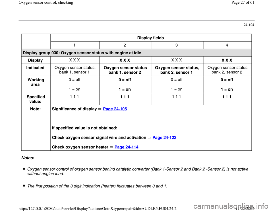
Display fields
1 2 3 4
Display group 030: Oxygen sensor status with engine at idle
Display X X X
X X X X X X
X X X
Indicated Oxygen sensor status,
bank 1, sensor 1 Oxygen sensor status
bank 1, sensor 2 Oxygen sensor status,
bank 2, sensor 1 Oxygen sensor status
bank 2, sensor 2
Working
area 0 = off
1 = on 0 = off
1 = on 0 = off
1 = on 0 = off
1 = on
Specified
value: 1 1 1
1 1 1 1 1 1
1 1 1
Note:
Significance of display Page 24
-105
If specified value is not obtained:
Check oxygen sensor signal wire and activation Page 24
-122
Check oxygen sensor heater Page 24
-114
Notes:
Oxygen sensor control of oxygen sensor behind catalytic converter (Bank 1-Sensor 2 and Bank 2 -Sensor 2) is not active
without engine load.
The first position of the 3 digit indication (heater) fluctuates between 0 and 1.
Pa
ge 27 of 61 Ox
yg
en sensor control, checkin
g
11/22/2002 htt
p://127.0.0.1:8080/audi/servlet/Dis
play?action=Goto&t
yp
e=re
pair&id=AUDI.B5.FU04.24.2
Page 31 of 61
24-106
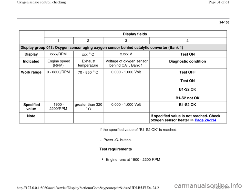
Display fields
1 2 3
4
Display group 043: Oxygen sensor aging oxygen sensor behind catalytic converter (Bank 1)
Display xxxx/RPM
xxx C
x.xxx V
Test ON
Indicated Engine speed
(RPM) Exhaust
temperature Voltage of oxygen sensor
behind CAT, Bank 1 Diagnostic condition
Work range 0 - 6800/RPM
70 - 850 C
0.000 - 1.000 Volt
Test OFF
Test ON
B1-S2 OK
B1-S2 not OK
Specified
value 1900 -
2200/RPM greater than 320
C 0.000 - 1.000 Volt
B1-S2 OK
Note
If specified value is not reached. Check
oxygen sensor heater Page 24
-114
If the specified value of "B1-S2 OK" is reached:
- Press -C- button.
Test requirements
Engine runs at 1900 - 2200 RPM
Pa
ge 31 of 61 Ox
yg
en sensor control, checkin
g
11/22/2002 htt
p://127.0.0.1:8080/audi/servlet/Dis
play?action=Goto&t
yp
e=re
pair&id=AUDI.B5.FU04.24.2
Page 33 of 61
24-107
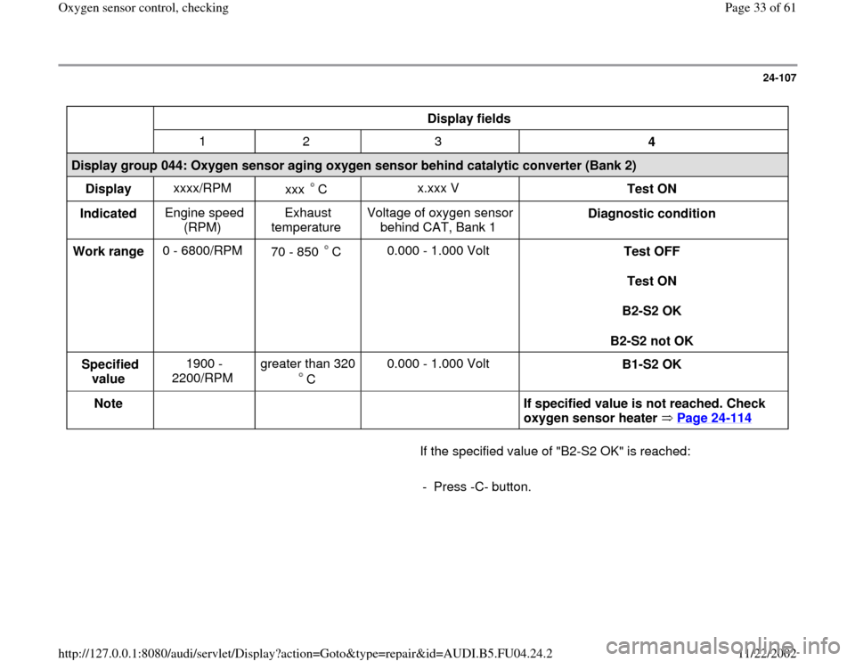
Display fields
1 2 3
4
Display group 044: Oxygen sensor aging oxygen sensor behind catalytic converter (Bank 2)
Display xxxx/RPM
xxx C
x.xxx V
Test ON
Indicated Engine speed
(RPM) Exhaust
temperature Voltage of oxygen sensor
behind CAT, Bank 1 Diagnostic condition
Work range 0 - 6800/RPM
70 - 850 C
0.000 - 1.000 Volt
Test OFF
Test ON
B2-S2 OK
B2-S2 not OK
Specified
value 1900 -
2200/RPM greater than 320
C 0.000 - 1.000 Volt
B1-S2 OK
Note
If specified value is not reached. Check
oxygen sensor heater Page 24
-114
If the specified value of "B2-S2 OK" is reached:
- Press -C- button.
Pa
ge 33 of 61 Ox
yg
en sensor control, checkin
g
11/22/2002 htt
p://127.0.0.1:8080/audi/servlet/Dis
play?action=Goto&t
yp
e=re
pair&id=AUDI.B5.FU04.24.2
Page 34 of 61
24-108
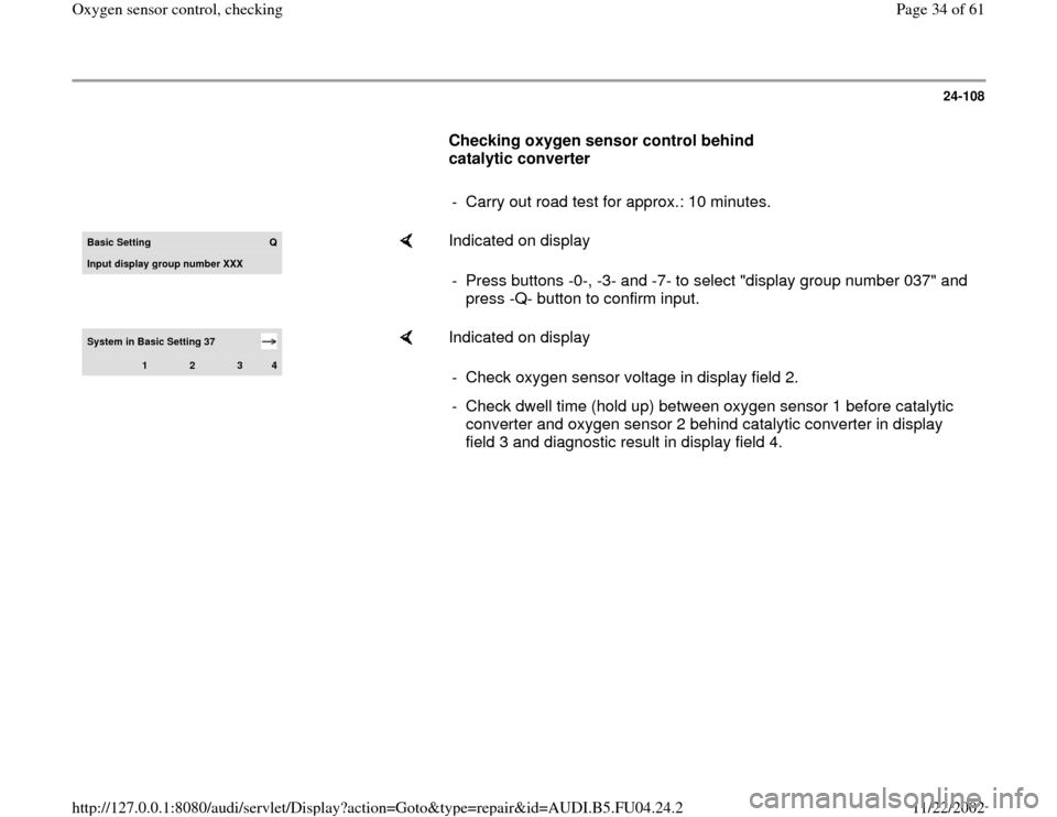
Checking oxygen sensor control behind
catalytic converter
- Carry out road test for approx.: 10 minutes.Basic Setting
Q
Input displa
y group number XXX
Indicated on display
- Press buttons -0-, -3- and -7- to select "display group number 037" and
press -Q- button to confirm input.
System in Basic Setting 37
1
2
3
4
Indicated on display
- Check oxygen sensor voltage in display field 2.
- Check dwell time (hold up) between oxygen sensor 1 before catalytic
converter and oxygen sensor 2 behind catalytic converter in display
field 3 and diagnostic result in display field 4.
Pa
ge 34 of 61 Ox
yg
en sensor control, checkin
g
11/22/2002 htt
p://127.0.0.1:8080/audi/servlet/Dis
play?action=Goto&t
yp
e=re
pair&id=AUDI.B5.FU04.24.2
Page 35 of 61
24-109
Display fields
1 2 3 4
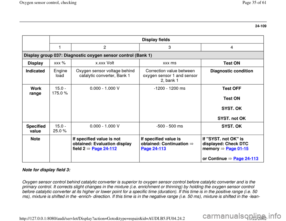
Display group 037: Diagnostic oxygen sensor control (Bank 1)
Display xxx % x.xxx Volt xxx ms
Test ON
Indicated Engine
load Oxygen sensor voltage behind
catalytic converter, Bank 1 Correction value between
oxygen sensor 1 and sensor
2, bank 1 Diagnostic condition
Work
range 15.0 -
175.0 % 0.000 - 1.000 V -1200 - 1200 ms
Test OFF
Test ON
SYST. OK
SYST. not OK
Specified
value 15.0 -
25.0 % 0.000 - 1.000 V -500 - 500 ms
SYST. OK
Note
If specified value is not
obtained: Evaluation display
field 2 Page 24
-112
If specified value is
obtained: Continuation
Page 24
-113
If "SYST. not OK" is
displayed: Check DTC
memory Page 01
-15
or Continue Page 24-113
Note for display field 3:
Oxygen sensor control behind catalytic converter is superior to oxygen sensor control before catalytic converter and is the
primary control. It corrects slight changes in the mixture (i.e. enrichment or thinning) by holding the oxygen sensor control
before catalytic converter at its higher or lower point for a specific time (duration). If this time is in the positive range (i.e. 50
ms), mixture is shifted in the -enrich- direction. If this time is in the negative range (i.e. 50 ms), mixture is shifted in the -lean-
Pa
ge 35 of 61 Ox
yg
en sensor control, checkin
g
11/22/2002 htt
p://127.0.0.1:8080/audi/servlet/Dis
play?action=Goto&t
yp
e=re
pair&id=AUDI.B5.FU04.24.2
Page 38 of 61
24-111
Display fields
1 2 3 4
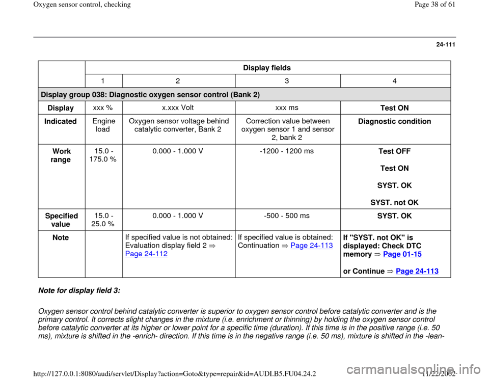
Display group 038: Diagnostic oxygen sensor control (Bank 2)
Display xxx % x.xxx Volt xxx ms
Test ON
Indicated Engine
load Oxygen sensor voltage behind
catalytic converter, Bank 2 Correction value between
oxygen sensor 1 and sensor
2, bank 2 Diagnostic condition
Work
range 15.0 -
175.0 % 0.000 - 1.000 V -1200 - 1200 ms
Test OFF
Test ON
SYST. OK
SYST. not OK
Specified
value 15.0 -
25.0 % 0.000 - 1.000 V -500 - 500 ms
SYST. OK
Note
If specified value is not obtained:
Evaluation display field 2
Page 24
-112
If specified value is obtained:
Continuation Page 24
-113
If "SYST. not OK" is
displayed: Check DTC
memory Page 01
-15
or Continue Page 24-113
Note for display field 3:
Oxygen sensor control behind catalytic converter is superior to oxygen sensor control before catalytic converter and is the
primary control. It corrects slight changes in the mixture (i.e. enrichment or thinning) by holding the oxygen sensor control
before catalytic converter at its higher or lower point for a specific time (duration). If this time is in the positive range (i.e. 50
ms), mixture is shifted in the -enrich- direction. If this time is in the negative range (i.e. 50 ms), mixture is shifted in the -lean-
Pa
ge 38 of 61 Ox
yg
en sensor control, checkin
g
11/22/2002 htt
p://127.0.0.1:8080/audi/servlet/Dis
play?action=Goto&t
yp
e=re
pair&id=AUDI.B5.FU04.24.2
Page 41 of 61
24-113
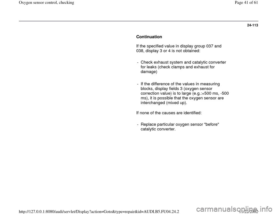
Continuation
If the specified value in display group 037 and
038, display 3 or 4 is not obtained:
- Check exhaust system and catalytic converter
for leaks (check clamps and exhaust for
damage)
- If the difference of the values in measuring
blocks, display fields 3 (oxygen sensor
correction value) is to large (e.g.:+500 ms, -500
ms), it is possible that the oxygen sensor are
interchanged (mixed up).
If none of the causes are identified:
- Replace particular oxygen sensor "before"
catalytic converter.
Pa
ge 41 of 61 Ox
yg
en sensor control, checkin
g
11/22/2002 htt
p://127.0.0.1:8080/audi/servlet/Dis
play?action=Goto&t
yp
e=re
pair&id=AUDI.B5.FU04.24.2
Page 48 of 61
24-120
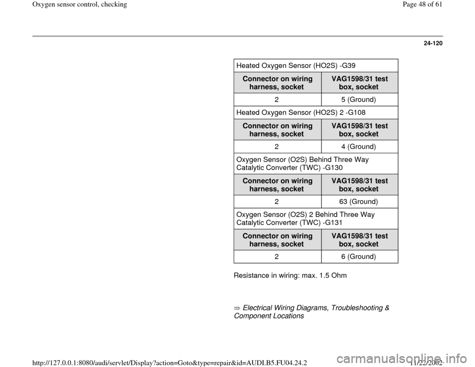
Heated Oxygen Sensor (HO2S) -G39
Connector on wiring
harness, socket
VAG1598/31 test
box, socket
2 5 (Ground)
Heated Oxygen Sensor (HO2S) 2 -G108
Connector on wiring
harness, socket
VAG1598/31 test
box, socket
2 4 (Ground)
Oxygen Sensor (O2S) Behind Three Way
Catalytic Converter (TWC) -G130
Connector on wiring
harness, socket
VAG1598/31 test
box, socket
2 63 (Ground)
Oxygen Sensor (O2S) 2 Behind Three Way
Catalytic Converter (TWC) -G131
Connector on wiring
harness, socket
VAG1598/31 test
box, socket
2 6 (Ground)
Resistance in wiring: max. 1.5 Ohm
Electrical Wiring Diagrams, Troubleshooting &
Component Locations
Pa
ge 48 of 61 Ox
yg
en sensor control, checkin
g
11/22/2002 htt
p://127.0.0.1:8080/audi/servlet/Dis
play?action=Goto&t
yp
e=re
pair&id=AUDI.B5.FU04.24.2
Page 53 of 61
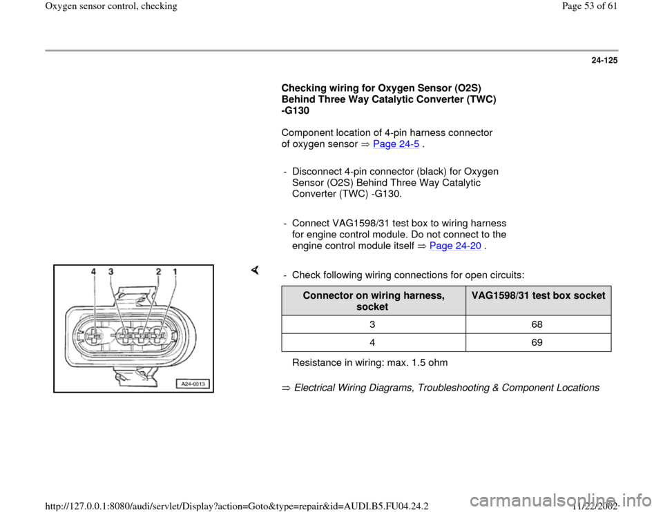
24-125
Checking wiring for Oxygen Sensor (O2S)
Behind Three Way Catalytic Converter (TWC)
-G130
Component location of 4-pin harness connector
of oxygen sensor Page 24
-5 .
- Disconnect 4-pin connector (black) for Oxygen
Sensor (O2S) Behind Three Way Catalytic
Converter (TWC) -G130.
- Connect VAG1598/31 test box to wiring harness
for engine control module. Do not connect to the
engine control module itself Page 24
-20
.
Electrical Wiring Diagrams, Troubleshooting & Component Locations - Check following wiring connections for open circuits:
Connector on wiring harness,
socket
VAG1598/31 test box socket
3 68
4 69
Resistance in wiring: max. 1.5 ohm
Pa
ge 53 of 61 Ox
yg
en sensor control, checkin
g
11/22/2002 htt
p://127.0.0.1:8080/audi/servlet/Dis
play?action=Goto&t
yp
e=re
pair&id=AUDI.B5.FU04.24.2
Page 57 of 61
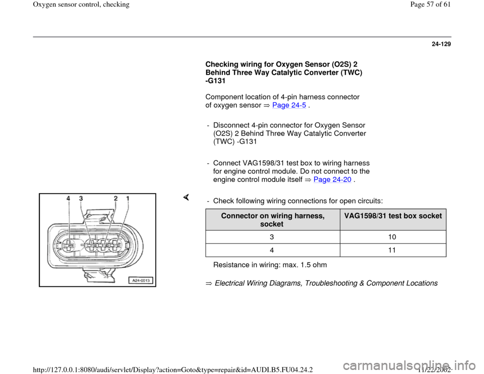
24-129
Checking wiring for Oxygen Sensor (O2S) 2
Behind Three Way Catalytic Converter (TWC)
-G131
Component location of 4-pin harness connector
of oxygen sensor Page 24
-5 .
- Disconnect 4-pin connector for Oxygen Sensor
(O2S) 2 Behind Three Way Catalytic Converter
(TWC) -G131
- Connect VAG1598/31 test box to wiring harness
for engine control module. Do not connect to the
engine control module itself Page 24
-20
.
Electrical Wiring Diagrams, Troubleshooting & Component Locations - Check following wiring connections for open circuits:
Connector on wiring harness,
socket
VAG1598/31 test box socket
3 10
4 11
Resistance in wiring: max. 1.5 ohm
Pa
ge 57 of 61 Ox
yg
en sensor control, checkin
g
11/22/2002 htt
p://127.0.0.1:8080/audi/servlet/Dis
play?action=Goto&t
yp
e=re
pair&id=AUDI.B5.FU04.24.2