AUDI A4 1998 B5 / 1.G 01V Transmission Read Measuring Value Block E 17 Owner's Manual
Manufacturer: AUDI, Model Year: 1998, Model line: A4, Model: AUDI A4 1998 B5 / 1.GPages: 49, PDF Size: 0.16 MB
Page 21 of 49
1) While driving, a second mechanic is required to read specifications. 2) Shift lock solenoid -N110- is also referred to as shift lock solenoid -N110-.
Pa
ge 21 of 49 Read Measurin
g Value Block
(scan tool function 08
) for transmissions with h
ydraulic control -E17-
11/20/2002 htt
p://127.0.0.1:8080/audi/servlet/Dis
play?action=Goto&t
yp
e=re
pair&id=AUDI.B5.AT02.01.13
Page 22 of 49
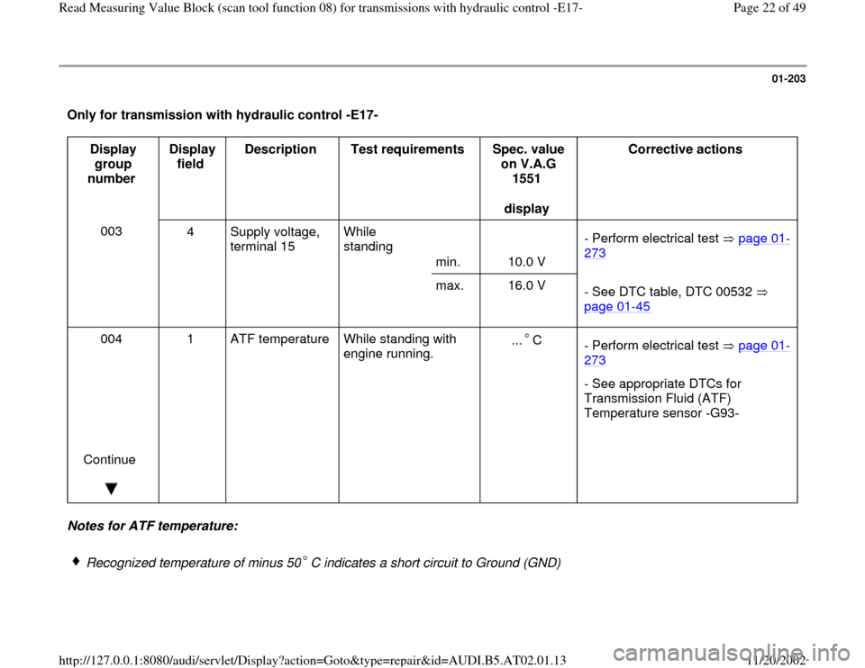
01-203
Only for transmission with hydraulic control -E17-
Display
group
number Display
field Description
Test requirements
Spec. value
on V.A.G
1551
display Corrective actions
003
4 Supply voltage,
terminal 15 While
standing
min.
10.0 V - Perform electrical test page 01
-
273
max. 16.0 V
- See DTC table, DTC 00532
page 01
-45
004
Continue
1 ATF temperature
While standing with
engine running. ... C
- Perform electrical test page 01
-
273
- See appropriate DTCs for
Transmission Fluid (ATF)
Temperature sensor -G93-
Notes for ATF temperature:
Recognized temperature of minus 50 C indicates a short circuit to Ground (GND)
Pa
ge 22 of 49 Read Measurin
g Value Block
(scan tool function 08
) for transmissions with h
ydraulic control -E17-
11/20/2002 htt
p://127.0.0.1:8080/audi/servlet/Dis
play?action=Goto&t
yp
e=re
pair&id=AUDI.B5.AT02.01.13
Page 23 of 49
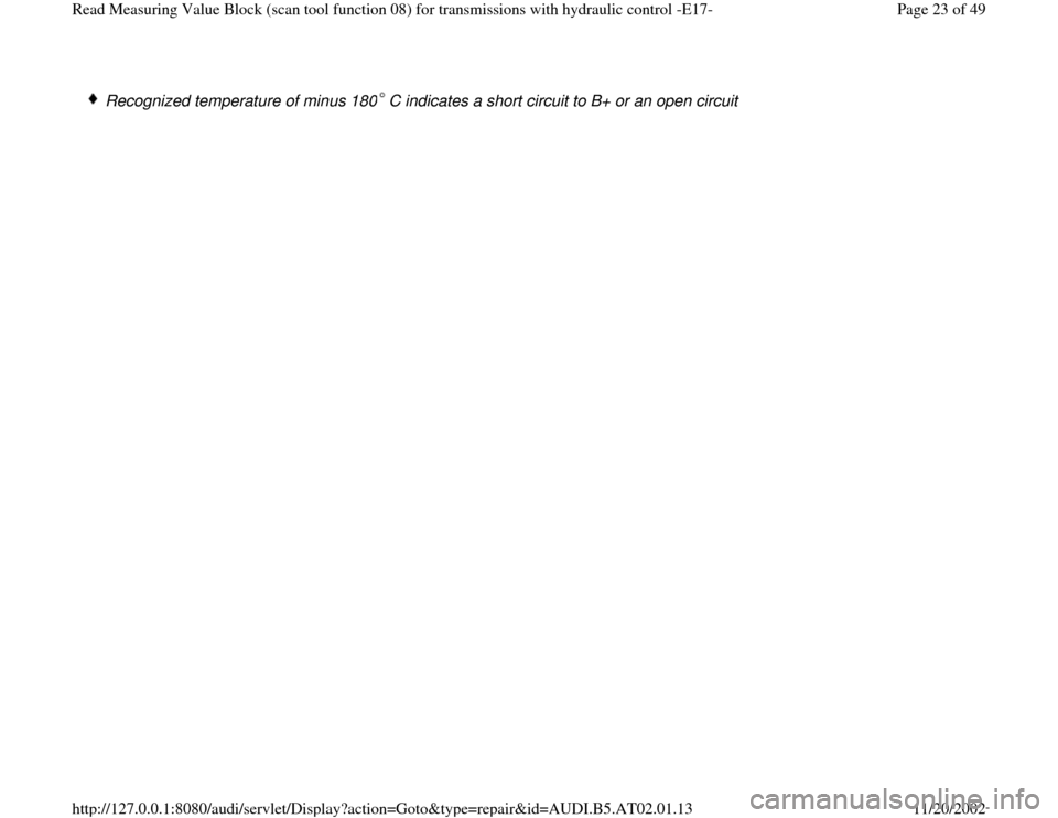
Recognized temperature of minus 180 C indicates a short circuit to B+ or an open circuit
Pa
ge 23 of 49 Read Measurin
g Value Block
(scan tool function 08
) for transmissions with h
ydraulic control -E17-
11/20/2002 htt
p://127.0.0.1:8080/audi/servlet/Dis
play?action=Goto&t
yp
e=re
pair&id=AUDI.B5.AT02.01.13
Page 24 of 49
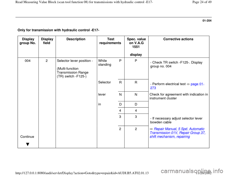
01-204
Only for transmission with hydraulic control -E17-
Display
group No. Display
field Description
Test
requirements Spec. value
on V.A.G
1551
display Corrective actions
004 2 Selector lever position -
(Multi-function
Transmission Range
(TR) switch -F125-) While
standing P P
- Check TR switch -F125-. Display
group no. 004
Selector
R R
- Perform electrical test page 01
-
273
lever
N N Check for agreement with indication in
instrument cluster
in
D D
4 4
3 3
- If necessary adjust selector lever
bowden cable
Continue
2 2 Repair Manual, 5 Spd. Automatic
Transmission 01V, Repair Group 37, shift mechanism, repairing
Pa
ge 24 of 49 Read Measurin
g Value Block
(scan tool function 08
) for transmissions with h
ydraulic control -E17-
11/20/2002 htt
p://127.0.0.1:8080/audi/servlet/Dis
play?action=Goto&t
yp
e=re
pair&id=AUDI.B5.AT02.01.13
Page 25 of 49
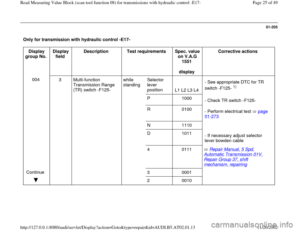
01-205
Only for transmission with hydraulic control -E17-
Display
group No. Display
field Description
Test requirements
Spec. value
on V.A.G
1551
display Corrective actions
004
3 Multi-function
Transmission Range
(TR) switch -F125- while
standing Selector
lever
position
L1 L2 L3 L4 - See appropriate DTC for TR
switch -F125-
1)
P 1000
- Check TR switch -F125-
R 0100
- Perform electrical test page
01
-273
N 1110
D 1011
- If necessary adjust selector
lever bowden cable
4 0111 Repair Manual, 5 Spd.
Automatic Transmission 01V, Repair Group 37, shift mechanism, repairing
Continue
3 0001
2 0010
Pa
ge 25 of 49 Read Measurin
g Value Block
(scan tool function 08
) for transmissions with h
ydraulic control -E17-
11/20/2002 htt
p://127.0.0.1:8080/audi/servlet/Dis
play?action=Goto&t
yp
e=re
pair&id=AUDI.B5.AT02.01.13
Page 26 of 49
01-206
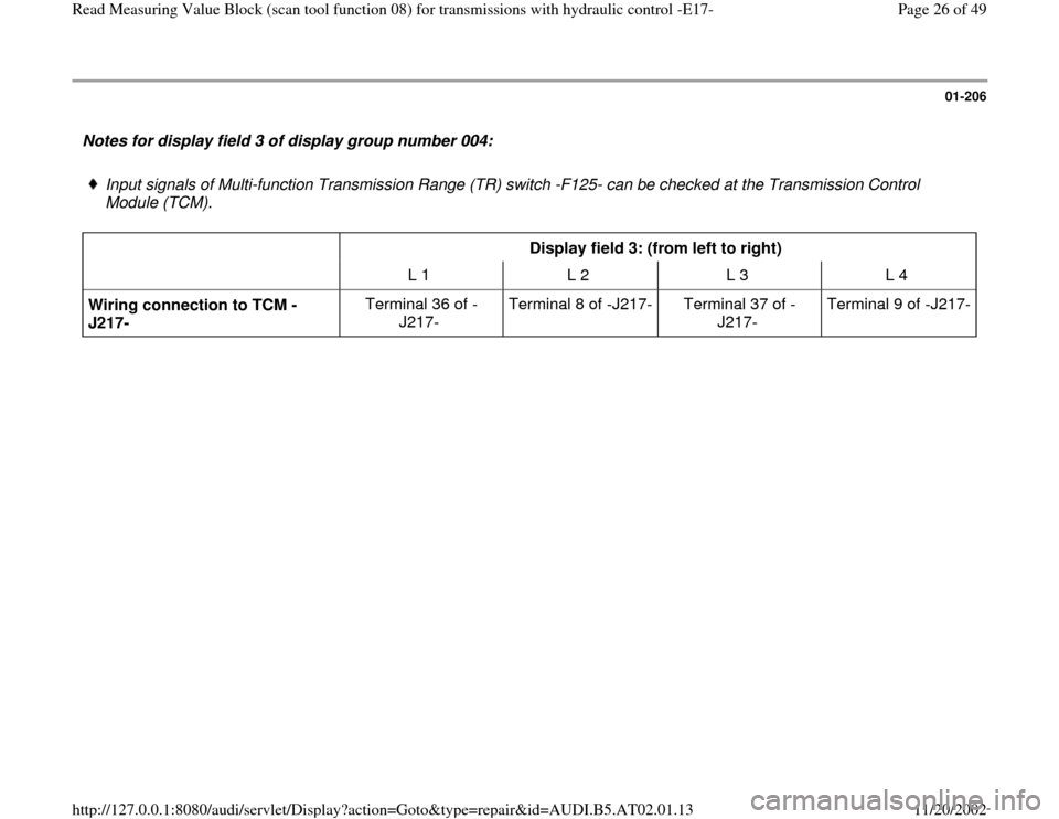
Notes for display field 3 of display group number 004:
Input signals of Multi-function Transmission Range (TR) switch -F125- can be checked at the Transmission Control
Module (TCM).
Display field 3: (from left to right)
L 1 L 2 L 3 L 4
Wiring connection to TCM -
J217- Terminal 36 of -
J217- Terminal 8 of -J217-
Terminal 37 of -
J217- Terminal 9 of -J217-
Pa
ge 26 of 49 Read Measurin
g Value Block
(scan tool function 08
) for transmissions with h
ydraulic control -E17-
11/20/2002 htt
p://127.0.0.1:8080/audi/servlet/Dis
play?action=Goto&t
yp
e=re
pair&id=AUDI.B5.AT02.01.13
Page 27 of 49
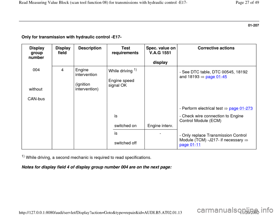
01-207
Only for transmission with hydraulic control -E17-
Display
group
number Display
field Description
Test
requirements Spec. value on
V.A.G 1551
display Corrective actions
004
without
CAN-bus 4 Engine
intervention
(ignition
intervention) While driving
1)
Engine speed
signal OK
- See DTC table, DTC 00545, 18192
and 18193 page 01
-45
is
switched on
Engine interv. - Perform electrical test page 01
-273
- Check wire connection to Engine
Control Module (ECM)
is
switched off -
- Only replace Transmission Control
Module (TCM) -J217- if necessary
page 01
-11
1) While driving, a second mechanic is required to read specifications.
Notes for display field 4 of display group number 004 are on the next page:
Pa
ge 27 of 49 Read Measurin
g Value Block
(scan tool function 08
) for transmissions with h
ydraulic control -E17-
11/20/2002 htt
p://127.0.0.1:8080/audi/servlet/Dis
play?action=Goto&t
yp
e=re
pair&id=AUDI.B5.AT02.01.13
Page 28 of 49
01-208
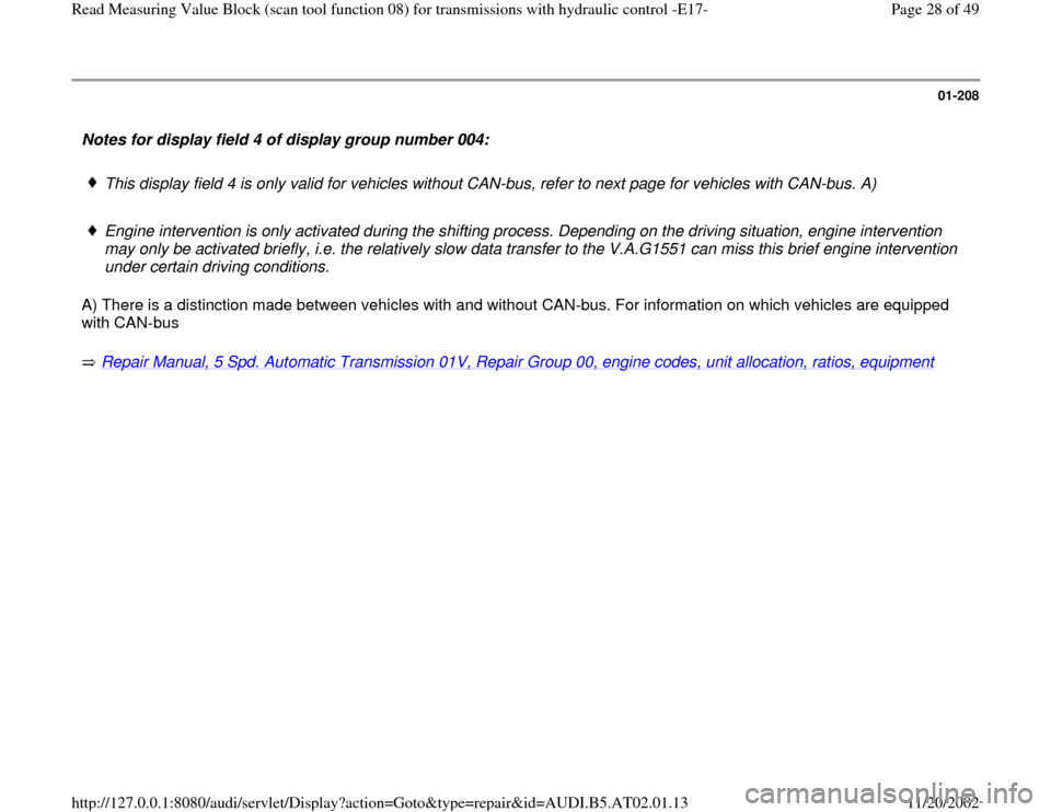
Notes for display field 4 of display group number 004:
This display field 4 is only valid for vehicles without CAN-bus, refer to next page for vehicles with CAN-bus. A)
Engine intervention is only activated during the shifting process. Depending on the driving situation, engine intervention
may only be activated briefly, i.e. the relatively slow data transfer to the V.A.G1551 can miss this brief engine intervention
under certain driving conditions.
A) There is a distinction made between vehicles with and without CAN-bus. For information on which vehicles are equipped
with CAN-bus
Repair Manual, 5 Spd. Automatic Transmission 01V, Repair Group 00, engine codes, unit allocation, ratios, equipment
Pa
ge 28 of 49 Read Measurin
g Value Block
(scan tool function 08
) for transmissions with h
ydraulic control -E17-
11/20/2002 htt
p://127.0.0.1:8080/audi/servlet/Dis
play?action=Goto&t
yp
e=re
pair&id=AUDI.B5.AT02.01.13
Page 29 of 49
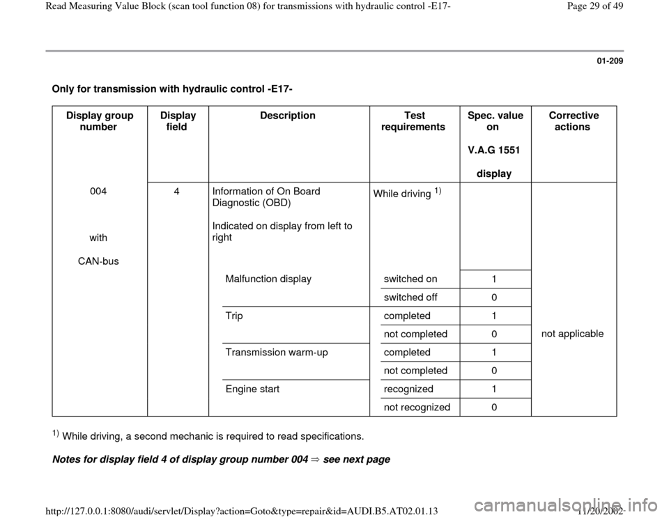
01-209
Only for transmission with hydraulic control -E17-
Display group
number Display
field Description
Test
requirements Spec. value
on
V.A.G 1551
display Corrective
actions
004
with
CAN-bus 4 Information of On Board
Diagnostic (OBD)
Indicated on display from left to
right While driving
1)
Malfunction display switched on
1
switched off 0
Trip completed 1
not completed 0 not applicable
Transmission warm-up
completed 1
not completed 0
Engine start
recognized 1
not recognized 0
1) While driving, a second mechanic is required to read specifications.
Notes for display field 4 of display group number 004 see next page
Pa
ge 29 of 49 Read Measurin
g Value Block
(scan tool function 08
) for transmissions with h
ydraulic control -E17-
11/20/2002 htt
p://127.0.0.1:8080/audi/servlet/Dis
play?action=Goto&t
yp
e=re
pair&id=AUDI.B5.AT02.01.13
Page 30 of 49
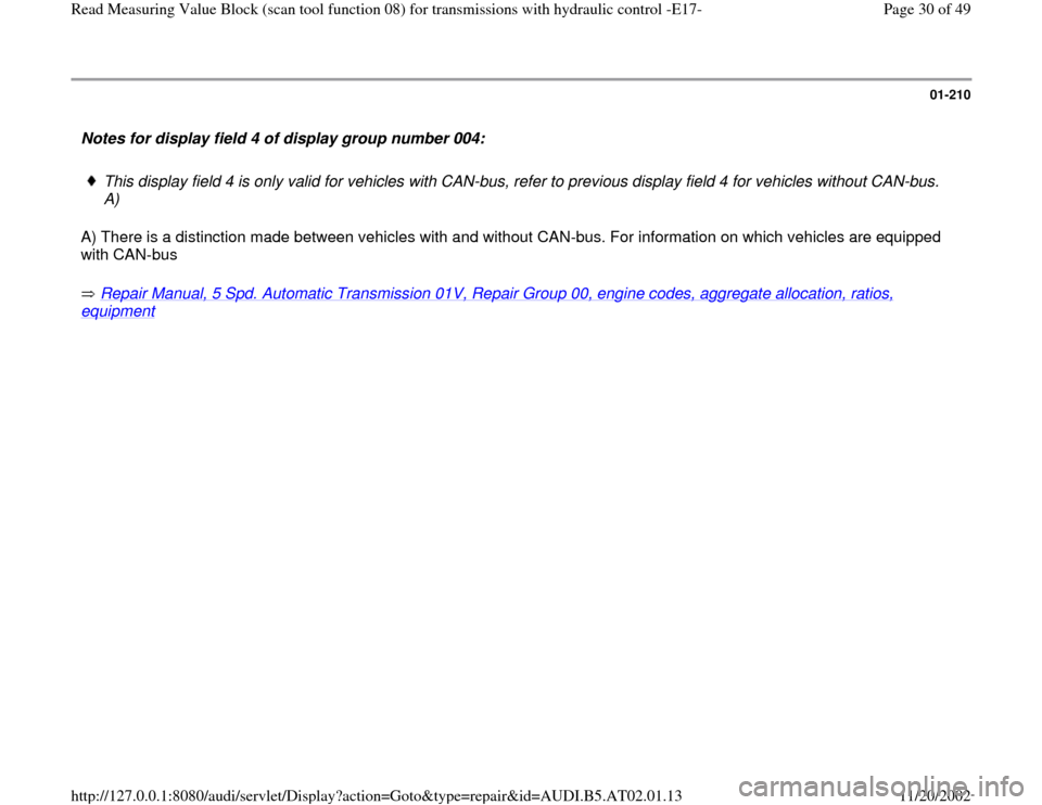
01-210
Notes for display field 4 of display group number 004:
This display field 4 is only valid for vehicles with CAN-bus, refer to previous display field 4 for vehicles without CAN-bus.
A)
A) There is a distinction made between vehicles with and without CAN-bus. For information on which vehicles are equipped
with CAN-bus
Repair Manual, 5 Spd. Automatic Transmission 01V, Repair Group 00, engine codes, aggregate allocation, ratios,
equipment
Pa
ge 30 of 49 Read Measurin
g Value Block
(scan tool function 08
) for transmissions with h
ydraulic control -E17-
11/20/2002 htt
p://127.0.0.1:8080/audi/servlet/Dis
play?action=Goto&t
yp
e=re
pair&id=AUDI.B5.AT02.01.13