ECO mode AUDI A4 1998 B5 / 1.G AC System On Board Diagnostic Workshop Manual
[x] Cancel search | Manufacturer: AUDI, Model Year: 1998, Model line: A4, Model: AUDI A4 1998 B5 / 1.GPages: 91, PDF Size: 0.32 MB
Page 4 of 91
01-3
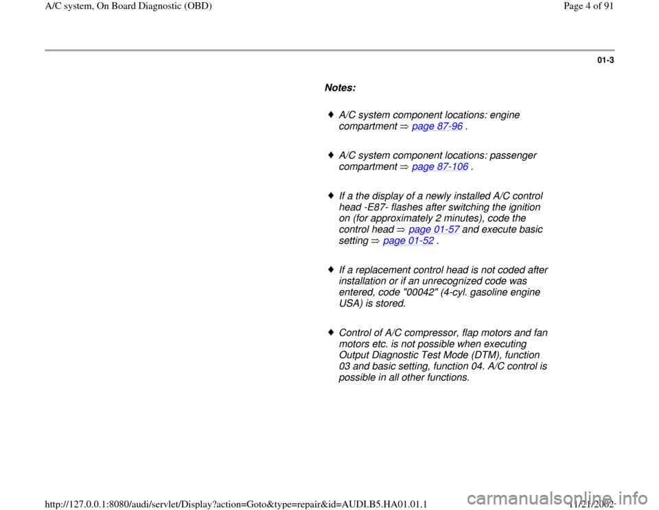
Notes:
A/C system component locations: engine
compartment page 87
-96
.
A/C system component locations: passenger
compartment page 87
-106
.
If a the display of a newly installed A/C control
head -E87- flashes after switching the ignition
on (for approximately 2 minutes), code the
control head page 01
-57
and execute basic
setting page 01
-52
.
If a replacement control head is not coded after
installation or if an unrecognized code was
entered, code "00042" (4-cyl. gasoline engine
USA) is stored.
Control of A/C compressor, flap motors and fan
motors etc. is not possible when executing
Output Diagnostic Test Mode (DTM), function
03 and basic setting, function 04. A/C control is
possible in all other functions.
Pa
ge 4 of 91 A/C s
ystem, On Board Dia
gnostic
(OBD
)
11/21/2002 htt
p://127.0.0.1:8080/audi/servlet/Dis
play?action=Goto&t
yp
e=re
pair&id=AUDI.B5.HA01.01.1
Page 28 of 91
01-22
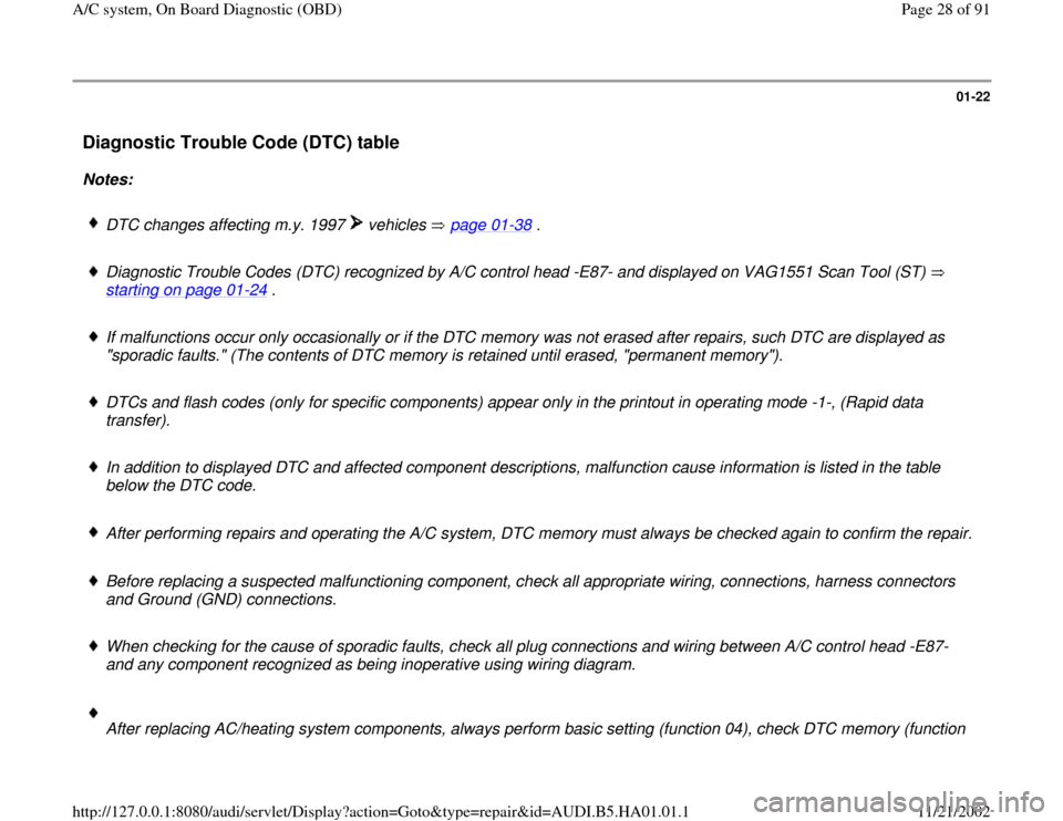
Diagnostic Trouble Code (DTC) table
Notes:
DTC changes affecting m.y. 1997 vehicles page 01
-38
.
Diagnostic Trouble Codes (DTC) recognized by A/C control head -E87- and displayed on VAG1551 Scan Tool (ST)
starting on page 01
-24
.
If malfunctions occur only occasionally or if the DTC memory was not erased after repairs, such DTC are displayed as
"sporadic faults." (The contents of DTC memory is retained until erased, "permanent memory").
DTCs and flash codes (only for specific components) appear only in the printout in operating mode -1-, (Rapid data
transfer).
In addition to displayed DTC and affected component descriptions, malfunction cause information is listed in the table
below the DTC code.
After performing repairs and operating the A/C system, DTC memory must always be checked again to confirm the repair.
Before replacing a suspected malfunctioning component, check all appropriate wiring, connections, harness connectors
and Ground (GND) connections.
When checking for the cause of sporadic faults, check all plug connections and wiring between A/C control head -E87-
and any component recognized as being inoperative using wiring diagram.
After replacing AC/heating system components, always perform basic setting (function 04), check DTC memory (function
Pa
ge 28 of 91 A/C s
ystem, On Board Dia
gnostic
(OBD
)
11/21/2002 htt
p://127.0.0.1:8080/audi/servlet/Dis
play?action=Goto&t
yp
e=re
pair&id=AUDI.B5.HA01.01.1
Page 30 of 91
01-23
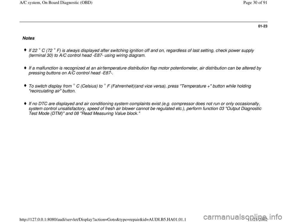
Notes
If 22 C (72 F) is always displayed after switching ignition off and on, regardless of last setting, check power supply
(terminal 30) to A/C control head -E87- using wiring diagram. If a malfunction is recognized at an air/temperature distribution flap motor potentiometer, air distribution can be altered by
pressing buttons on A/C control head -E87-.
To switch display from C (Celsius) to F (Fahrenheit)(and vice versa), press "Temperature +" button while holding
"recirculating air" button. If no DTC are displayed and air conditioning system complaints exist (e.g. compressor does not run or only occasionally,
system control unsatisfactory, speed of fresh air blower cannot be regulated etc.), perform function 03 "Output Diagnostic
Test Mode (DTM)" and 08 "Read Measuring Value block."
Pa
ge 30 of 91 A/C s
ystem, On Board Dia
gnostic
(OBD
)
11/21/2002 htt
p://127.0.0.1:8080/audi/servlet/Dis
play?action=Goto&t
yp
e=re
pair&id=AUDI.B5.HA01.01.1
Page 31 of 91
01-24
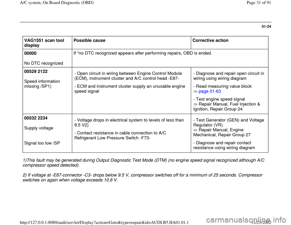
VAG1551 scan tool
display Possible cause
Corrective action
00000
No DTC recognized If "no DTC recognized appears after performing repairs, OBD is ended.
00529 2122
Speed information
missing /SP1) - Open circuit in wiring between Engine Control Module
(ECM), instrument cluster and A/C control head -E87-
- ECM and instrument cluster supply an unusable engine
speed signal - Diagnose and repair open circuit in
wiring using wiring diagram
- Read measuring value block
page 01
-63
- Test engine speed signal
Repair Manual, Fuel Injection &
Ignition, Repair Group 24
00532 2234
Supply voltage
Signal too low /SP - Voltage drops in electrical system to levels of less than
9.5 V2)
- Contact resistance in cable connection to A/C
Refrigerant Low Pressure Switch -F73- - Test Generator (GEN) and Voltage
Regulator (VR)
Repair Manual, Engine
Mechanical, Repair Group 27
- Diagnose and repair contact
resistance using wiring diagram
1)This fault may be generated during Output Diagnostic Test Mode (DTM) (no engine speed signal recognized although A/C
compressor speed detected).
2) If voltage at -E87-connector -C3- drops below 9.5 V, compressor switches off for a minimum of 25 seconds. Compressor
switches on again when voltage exceeds 10.8 V.
Pa
ge 31 of 91 A/C s
ystem, On Board Dia
gnostic
(OBD
)
11/21/2002 htt
p://127.0.0.1:8080/audi/servlet/Dis
play?action=Goto&t
yp
e=re
pair&id=AUDI.B5.HA01.01.1
Page 47 of 91
1) Continued from page 01
-34
.
2) Compressor cannot be switched off (this fault is recognized only during Output Diagnosis Test Mode (DTM)).
Pa
ge 47 of 91 A/C s
ystem, On Board Dia
gnostic
(OBD
)
11/21/2002 htt
p://127.0.0.1:8080/audi/servlet/Dis
play?action=Goto&t
yp
e=re
pair&id=AUDI.B5.HA01.01.1
Page 63 of 91
01-45
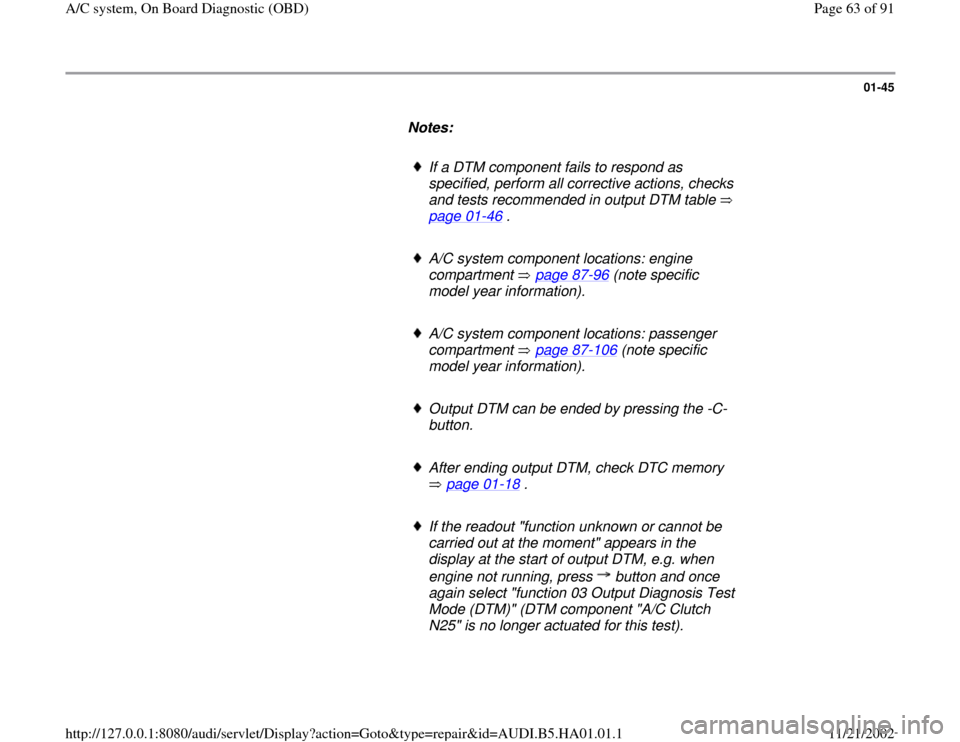
Notes:
If a DTM component fails to respond as
specified, perform all corrective actions, checks
and tests recommended in output DTM table
page 01
-46
.
A/C system component locations: engine
compartment page 87
-96
(note specific
model year information).
A/C system component locations: passenger
compartment page 87
-106
(note specific
model year information).
Output DTM can be ended by pressing the -C-
button.
After ending output DTM, check DTC memory
page 01
-18
.
If the readout "function unknown or cannot be
carried out at the moment" appears in the
display at the start of output DTM, e.g. when
engine not running, press button and once
again select "function 03 Output Diagnosis Test
Mode (DTM)" (DTM component "A/C Clutch
N25" is no longer actuated for this test).
Pa
ge 63 of 91 A/C s
ystem, On Board Dia
gnostic
(OBD
)
11/21/2002 htt
p://127.0.0.1:8080/audi/servlet/Dis
play?action=Goto&t
yp
e=re
pair&id=AUDI.B5.HA01.01.1
Page 65 of 91
01-46
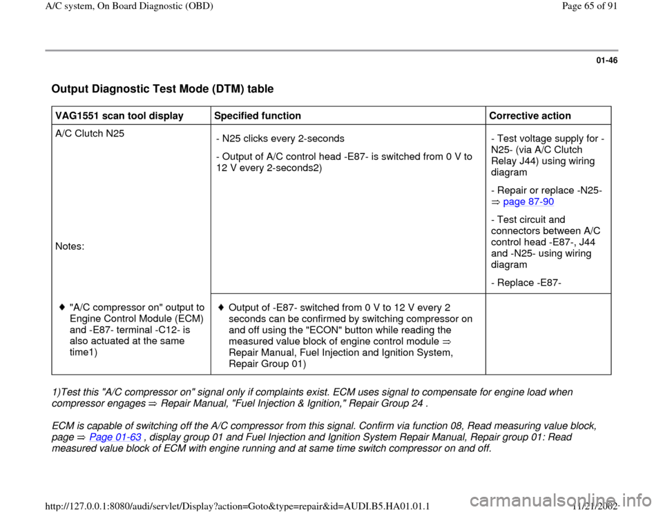
Output Diagnostic Test Mode (DTM) table
VAG1551 scan tool display
Specified function
Corrective action
A/C Clutch N25
Notes: - N25 clicks every 2-seconds
- Output of A/C control head -E87- is switched from 0 V to
12 V every 2-seconds2) - Test voltage supply for -
N25- (via A/C Clutch
Relay J44) using wiring
diagram
- Repair or replace -N25-
page 87
-90
- Test circuit and
connectors between A/C
control head -E87-, J44
and -N25- using wiring
diagram
- Replace -E87-
"A/C compressor on" output to
Engine Control Module (ECM)
and -E87- terminal -C12- is
also actuated at the same
time1)
Output of -E87- switched from 0 V to 12 V every 2
seconds can be confirmed by switching compressor on
and off using the "ECON" button while reading the
measured value block of engine control module
Repair Manual, Fuel Injection and Ignition System,
Repair Group 01)
1)Test this "A/C compressor on" signal only if complaints exist. ECM uses signal to compensate for engine load when
compressor engages Repair Manual, "Fuel Injection & Ignition," Repair Group 24 . ECM is capable of switching off the A/C compressor from this signal. Confirm via function 08, Read measuring value block,
page Page 01
-63
, display group 01 and Fuel Injection and Ignition System Repair Manual, Repair group 01: Read
measured value block of ECM with engine running and at same time switch compressor on and off.
Pa
ge 65 of 91 A/C s
ystem, On Board Dia
gnostic
(OBD
)
11/21/2002 htt
p://127.0.0.1:8080/audi/servlet/Dis
play?action=Goto&t
yp
e=re
pair&id=AUDI.B5.HA01.01.1