heating AUDI A4 1998 B5 / 1.G AC System On Board Diagnostic Workshop Manual
[x] Cancel search | Manufacturer: AUDI, Model Year: 1998, Model line: A4, Model: AUDI A4 1998 B5 / 1.GPages: 91, PDF Size: 0.32 MB
Page 2 of 91
01-2
Notes:
This Repair Manual describes On Board
Diagnostic (OBD) with VAG1551 Scan Tool
(ST). OBD procedures can also be performed
with VAG1552 Scan Tool (ST) (VAG1552 Scan
Tool is not equipped with a printer).
Scan Tool VAG1551 or 1552 must be used in in
operating mode -1- (Rapid data transfer).
Operating mode -2- (Flash code output) is not
provided for A/C and Heating OBD.
Always check DTC memory and perform
necessary repairs before erasing DTC memory.
DTC output is possible only if ignition is on or
engine is running and engine speed is less than
3000 rpm (if engine speed is higher, output is
possible only for a limited time or is terminated).
If a fault exists for a certain time it is stored as a
static fault.
If a static fault is no longer present after a
certain time, it is stored as a sporadic fault and
the reference "SP" appears on the upper right
of the VAG1551 display/print-out.
Pa
ge 2 of 91 A/C s
ystem, On Board Dia
gnostic
(OBD
)
11/21/2002 htt
p://127.0.0.1:8080/audi/servlet/Dis
play?action=Goto&t
yp
e=re
pair&id=AUDI.B5.HA01.01.1
Page 5 of 91
01-4
Heating and A/C system changes, 1997
On Board Diagnostic changes
New A/C control head -E87- with specific
coding for m.y. 1997, 4-cyl. and 6-cyl. engines.
Notes:
Before performing On Board Diagnostic of A/C
system, ensure A/C control head -E87- is coded
correctly (according to engine application).
A/C control heads beginning with Part No. 8L0
820 043 should only be installed in m.y. 1997
vehicles.
A/C control heads beginning with Part No. 8D0
820 043 must only be installed in vehicles
through m.y. 1996.
CAUTION!
Part numbers are for reference only.
Always check with your Parts Dept. for the
latest information.
Pa
ge 5 of 91 A/C s
ystem, On Board Dia
gnostic
(OBD
)
11/21/2002 htt
p://127.0.0.1:8080/audi/servlet/Dis
play?action=Goto&t
yp
e=re
pair&id=AUDI.B5.HA01.01.1
Page 10 of 91
01-7
A/C system changes
Revised heating/air conditioner assembly with
flap motors page 87
-174
.
The air flow flap motor now activates the fresh
air/recirculating air flap as well.
The two way valve for the circulating/fresh air
door, the vacuum unit and the vacuum reservoir
are deleted.
A/C refrigerant circuit changes
New service valve connection on low pressure
side.
Service valve connection for high pressure side
installed in high pressure line in plenum panel
(deleted at condenser).
A/C pressure switch -F129- replaces pressure
switches -F73- and -F118-.
New version "Zexel" compressor and high
pressure line (4-cyl. engines only).
Pa
ge 10 of 91 A/C s
ystem, On Board Dia
gnostic
(OBD
)
11/21/2002 htt
p://127.0.0.1:8080/audi/servlet/Dis
play?action=Goto&t
yp
e=re
pair&id=AUDI.B5.HA01.01.1
Page 14 of 91
01-11
- Press button -1- for operating mode "Rapid data
transfer." Rapid data transfer
HELP
Enter address word XX
Indicated on display
Notes:
If display is blank, check wiring to VAG1551/power supply using
Troubleshooting Procedure No. 1 in "Electrical Wiring Diagrams,
Troubleshooting and Component Locations" Manual.
Address word for A/C Heating Electronics: 08
Additional operating instructions can be obtained by pressing the
HELP button on VAG1551 Scan Tool (ST) During testing procedures, the button advances the program to the
next step An incorrect entry can be cancelled with the -C- button
- Press buttons -0- and -8-.
Rapid data transfer
Q
08 - A/C Heating Electronics
Indicated on display
- Press -Q- button to confirm input.
Pa
ge 14 of 91 A/C s
ystem, On Board Dia
gnostic
(OBD
)
11/21/2002 htt
p://127.0.0.1:8080/audi/servlet/Dis
play?action=Goto&t
yp
e=re
pair&id=AUDI.B5.HA01.01.1
Page 15 of 91
01-12
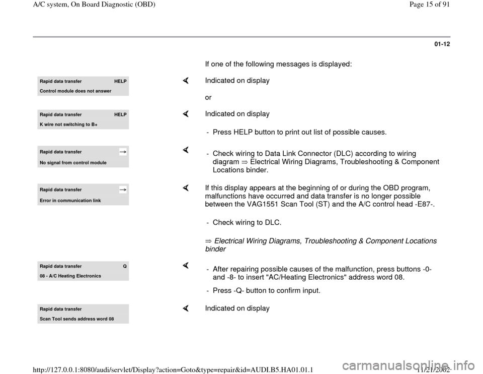
If one of the following messages is displayed: Rapid data transfer
HELP
Control module does not answer
Indicated on display
or
Rapid data transfer
HELP
K wire not switchin
g to B+
Indicated on display
- Press HELP button to print out list of possible causes.
Rapid data transfer No si
gnal from control module
- Check wiring to Data Link Connector (DLC) according to wiring
diagram Electrical Wiring Diagrams, Troubleshooting & Component
Locations binder.
Rapid data transfer Error in communication link
If this display appears at the beginning of or during the OBD program,
malfunctions have occurred and data transfer is no longer possible
between the VAG1551 Scan Tool (ST) and the A/C control head -E87-.
Electrical Wiring Diagrams, Troubleshooting & Component Locations
binder - Check wiring to DLC.
Rapid data transfer
Q
08 - A/C Heatin
g Electronics
- After repairing possible causes of the malfunction, press buttons -0-
and -8- to insert "AC/Heating Electronics" address word 08.
- Press -Q- button to confirm input.
Rapid data transfer Scan Tool sends address word 08
Indicated on display
Pa
ge 15 of 91 A/C s
ystem, On Board Dia
gnostic
(OBD
)
11/21/2002 htt
p://127.0.0.1:8080/audi/servlet/Dis
play?action=Goto&t
yp
e=re
pair&id=AUDI.B5.HA01.01.1
Page 16 of 91
01-13
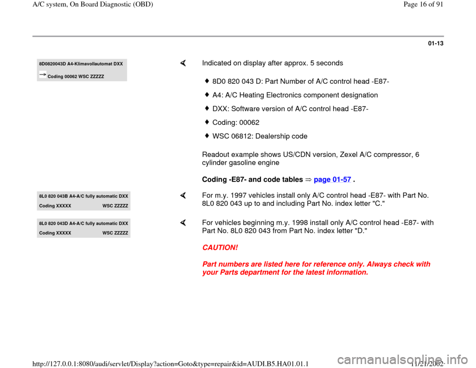
8D0820043D A4-Klimavollautomat DXX
Coding 00062 WSC ZZZZZ
Indicated on display after approx. 5 seconds
Readout example shows US/CDN version, Zexel A/C compressor, 6
cylinder gasoline engine
Coding -E87- and code tables page 01
-57
.
8D0 820 043 D: Part Number of A/C control head -E87-A4: A/C Heating Electronics component designationDXX: Software version of A/C control head -E87-Coding: 00062WSC 06812: Dealership code
8L0 820 043B A4-
A/C full
y automatic DXX
Codin
g XXXXX
WSC ZZZZZ
For m.y. 1997 vehicles install only A/C control head -E87- with Part No.
8L0 820 043 up to and including Part No. index letter "C."
8L0 820 043D A4-
A/C full
y automatic DXX
Coding XXXXX
WSC ZZZZZ
For vehicles beginning m.y. 1998 install only A/C control head -E87- with
Part No. 8L0 820 043 from Part No. index letter "D."
CAUTION!
Part numbers are listed here for reference only. Always check with
your Parts department for the latest information.
Pa
ge 16 of 91 A/C s
ystem, On Board Dia
gnostic
(OBD
)
11/21/2002 htt
p://127.0.0.1:8080/audi/servlet/Dis
play?action=Goto&t
yp
e=re
pair&id=AUDI.B5.HA01.01.1
Page 21 of 91
01-17
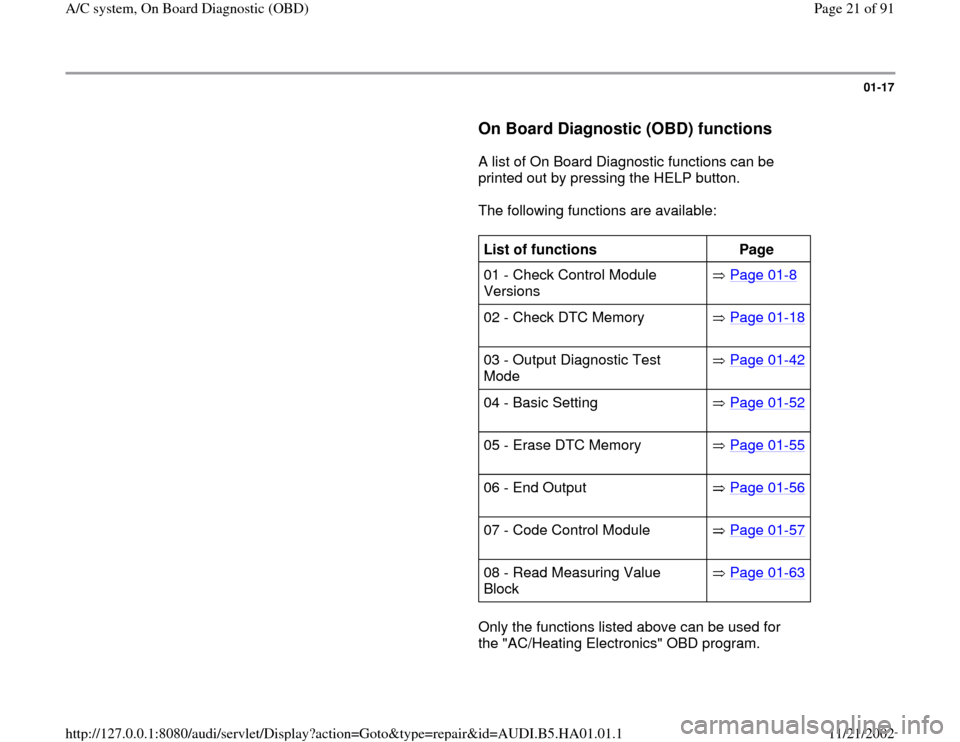
On Board Diagnostic (OBD) functions
A list of On Board Diagnostic functions can be
printed out by pressing the HELP button.
The following functions are available:
List of functions
Page
01 - Check Control Module
Versions Page 01
-8
02 - Check DTC Memory Page 01
-18
03 - Output Diagnostic Test
Mode Page 01
-42
04 - Basic Setting Page 01
-52
05 - Erase DTC Memory Page 01
-55
06 - End Output Page 01
-56
07 - Code Control Module Page 01
-57
08 - Read Measuring Value
Block Page 01
-63
Only the functions listed above can be used for
the "AC/Heating Electronics" OBD program.
Pa
ge 21 of 91 A/C s
ystem, On Board Dia
gnostic
(OBD
)
11/21/2002 htt
p://127.0.0.1:8080/audi/servlet/Dis
play?action=Goto&t
yp
e=re
pair&id=AUDI.B5.HA01.01.1
Page 23 of 91
01-18
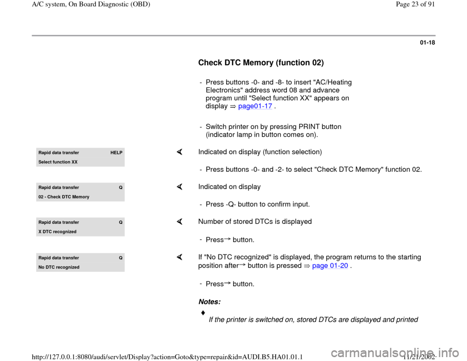
Check DTC Memory (function 02)
- Press buttons -0- and -8- to insert "AC/Heating
Electronics" address word 08 and advance
program until "Select function XX" appears on
display page01
-17
.
- Switch printer on by pressing PRINT button
(indicator lamp in button comes on). Rapid data transfer
HELP
Select function XX
Indicated on display (function selection)
- Press buttons -0- and -2- to select "Check DTC Memory" function 02.
Rapid data transfer
Q
02 - Check DTC Memor
y
Indicated on display
- Press -Q- button to confirm input.
Rapid data transfer
Q
X DTC reco
gnized
Number of stored DTCs is displayed
-
Press button.
Rapid data transfer
Q
No DTC reco
gnized
If "No DTC recognized" is displayed, the program returns to the starting
position after button is pressed page 01
-20
.
Notes:
-
Press button.
If the printer is switched on, stored DTCs are displayed and printed
Pa
ge 23 of 91 A/C s
ystem, On Board Dia
gnostic
(OBD
)
11/21/2002 htt
p://127.0.0.1:8080/audi/servlet/Dis
play?action=Goto&t
yp
e=re
pair&id=AUDI.B5.HA01.01.1
Page 27 of 91
01-21
Notes:
1997 If A/C control head -E87- is unable to
determine the duration of time when ignition is
off ("standing time"), DTC 01206 "signal for time
span ignition off" is loaded into memory. The
A/C control head will then default to a standing
time greater than 4 hours. The actual measured
values of the outside temperature sensor are
then used as instantaneous outside and engine
temperature inputs for A/C system control.
When the "heating" mode is selected under
these conditions, fresh air blower -V2- has a
delayed start (even when the actual standing
time is less than 4 hours and the engine is
warm) page 01
-86
, Read Measuring Value
Block. The outside air temperature display -
G106- may also indicate incorrect outside
temperature values.
If both display fields of the A/C control head do
not light with ignition switched on check control
head coding Page 01
-57
.
Pa
ge 27 of 91 A/C s
ystem, On Board Dia
gnostic
(OBD
)
11/21/2002 htt
p://127.0.0.1:8080/audi/servlet/Dis
play?action=Goto&t
yp
e=re
pair&id=AUDI.B5.HA01.01.1
Page 28 of 91
01-22
Diagnostic Trouble Code (DTC) table
Notes:
DTC changes affecting m.y. 1997 vehicles page 01
-38
.
Diagnostic Trouble Codes (DTC) recognized by A/C control head -E87- and displayed on VAG1551 Scan Tool (ST)
starting on page 01
-24
.
If malfunctions occur only occasionally or if the DTC memory was not erased after repairs, such DTC are displayed as
"sporadic faults." (The contents of DTC memory is retained until erased, "permanent memory").
DTCs and flash codes (only for specific components) appear only in the printout in operating mode -1-, (Rapid data
transfer).
In addition to displayed DTC and affected component descriptions, malfunction cause information is listed in the table
below the DTC code.
After performing repairs and operating the A/C system, DTC memory must always be checked again to confirm the repair.
Before replacing a suspected malfunctioning component, check all appropriate wiring, connections, harness connectors
and Ground (GND) connections.
When checking for the cause of sporadic faults, check all plug connections and wiring between A/C control head -E87-
and any component recognized as being inoperative using wiring diagram.
After replacing AC/heating system components, always perform basic setting (function 04), check DTC memory (function
Pa
ge 28 of 91 A/C s
ystem, On Board Dia
gnostic
(OBD
)
11/21/2002 htt
p://127.0.0.1:8080/audi/servlet/Dis
play?action=Goto&t
yp
e=re
pair&id=AUDI.B5.HA01.01.1