diagram AUDI A4 1998 B5 / 1.G APB Engine Additional Signals Checking Workshop Manual
[x] Cancel search | Manufacturer: AUDI, Model Year: 1998, Model line: A4, Model: AUDI A4 1998 B5 / 1.GPages: 37, PDF Size: 0.14 MB
Page 1 of 37
24-179
Additional signals, checking
Engine speed (RPM) signal, checking
Note:
The engine speed signal is taken from terminal
37 on the Engine Control Module (ECM). The
signal is used for various functions including the
RPM display in the instrument cluster.
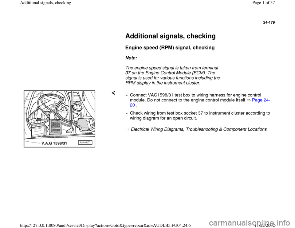
Electrical Wiring Diagrams, Troubleshooting & Component Locations - Connect VAG1598/31 test box to wiring harness for engine control
module. Do not connect to the engine control module itself Page 24
-
20
.
- Check wiring from test box socket 37 to instrument cluster according to
wiring diagram for an open circuit.
Pa
ge 1 of 37 Additional si
gnals, checkin
g
11/22/2002 htt
p://127.0.0.1:8080/audi/servlet/Dis
play?action=Goto&t
yp
e=re
pair&id=AUDI.B5.FU04.24.6
Page 2 of 37
24-180
Fuel consumption signal for on-board
computer, checking
Notes:
The fuel consumption signal is calculated by the
engine control module (on the basis of the
injection period) and passed on to the on-board
computer. The fuel consumption signal is taken
from terminal 81 on the Engine Control Module
(ECM).
Checking fuel consumption signal
Electrical Wiring Diagrams, Troubleshooting &
Component Locations
Pa
ge 2 of 37 Additional si
gnals, checkin
g
11/22/2002 htt
p://127.0.0.1:8080/audi/servlet/Dis
play?action=Goto&t
yp
e=re
pair&id=AUDI.B5.FU04.24.6
Page 3 of 37
24-181
Coolant temperature signal, checking
Notes:
The engine control module receives the coolant
temperature signal from the instrument cluster.
When the signal is received, the charge
pressure is reduced to prevent the engine from
overheating.
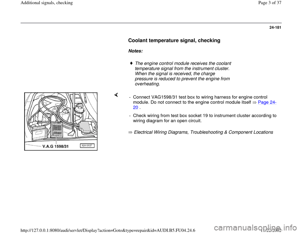
Electrical Wiring Diagrams, Troubleshooting & Component Locations - Connect VAG1598/31 test box to wiring harness for engine control
module. Do not connect to the engine control module itself Page 24
-
20
.
- Check wiring from test box socket 19 to instrument cluster according to
wiring diagram for an open circuit.
Pa
ge 3 of 37 Additional si
gnals, checkin
g
11/22/2002 htt
p://127.0.0.1:8080/audi/servlet/Dis
play?action=Goto&t
yp
e=re
pair&id=AUDI.B5.FU04.24.6
Page 6 of 37
24-183
- Take vehicle for a test drive and check whether
vehicle speed appears in display field 3.
- If vehicle speed does not appear, raise the
vehicle (preferably using a lift) until front left
wheel is clear of the ground.
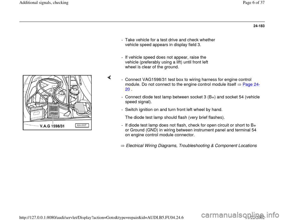
Electrical Wiring Diagrams, Troubleshooting & Component Locations - Connect VAG1598/31 test box to wiring harness for engine control
module. Do not connect to the engine control module itself Page 24
-
20
.
- Connect diode test lamp between socket 3 (B+) and socket 54 (vehicle
speed signal).
- Switch ignition on and turn front left wheel by hand.
The diode test lamp should flash (very brief flashes).
- If diode test lamp does not flash, check for open circuit or short to B+
or Ground (GND) in wiring between instrument panel and terminal 54
on engine control module connector.
Pa
ge 6 of 37 Additional si
gnals, checkin
g
11/22/2002 htt
p://127.0.0.1:8080/audi/servlet/Dis
play?action=Goto&t
yp
e=re
pair&id=AUDI.B5.FU04.24.6
Page 7 of 37
24-184
Fuel tank level signal, checking
Note:
The Engine Control Module (ECM) receives the
fuel tank level signal from the instrument
cluster.
The processed signal enters on terminal 30 the
Engine Control Module (ECM) and is used to
determine certain malfunctions (e.g.: misfire)
- Connect VAG1598/31 test box to wiring harness
for engine control module. Do not connect to the
engine control module itself Page 24
-20
.
- Check wiring from test box socket 30 to
instrument cluster according to wiring diagram
for an open circuit and short circuit to B+/Ground
(GND).
Pa
ge 7 of 37 Additional si
gnals, checkin
g
11/22/2002 htt
p://127.0.0.1:8080/audi/servlet/Dis
play?action=Goto&t
yp
e=re
pair&id=AUDI.B5.FU04.24.6
Page 13 of 37
Electrical Wiring Diagrams, Troubleshooting &
Component Locations
- If necessary eliminate open circuit or short
circuit to Ground (GND)
Pa
ge 13 of 37 Additional si
gnals, checkin
g
11/22/2002 htt
p://127.0.0.1:8080/audi/servlet/Dis
play?action=Goto&t
yp
e=re
pair&id=AUDI.B5.FU04.24.6
Page 20 of 37
24-194
If specification is obtained:
Check voltage supply
- Connect VAG1527 B between following sockets
on harness connector:
Harness connector
terminal
Measure
against
2 Ground (GND)
- Switch ignition on.
The LED must come on
If LED does not come on:
- Check wire connection from terminal 2 of
connector for open circuit (fuse) or short circuit
to Ground (GND).
Electrical Wiring Diagrams, Troubleshooting &
Component Locations
- If necessary eliminate open circuit or short
circuit to Ground (GND)
Pa
ge 20 of 37 Additional si
gnals, checkin
g
11/22/2002 htt
p://127.0.0.1:8080/audi/servlet/Dis
play?action=Goto&t
yp
e=re
pair&id=AUDI.B5.FU04.24.6
Page 23 of 37
24-197
Test the following wiring connections for open
circuit and/or short to B+ or Ground (GND) and
open circuit.
VAG1598/31 test
box, socket
Airbag control module,
contact
67 Electrical Wiring Diagrams,
Troubleshooting & Component
Locations
Resistance in wiring: max. 1.5 ohm
Eliminate open circuit or short circuit.
Electrical Wiring Diagrams, Troubleshooting &
Component Locations If no malfunctions are found in wiring: Check
DTC memory of airbag control module.
Pa
ge 23 of 37 Additional si
gnals, checkin
g
11/22/2002 htt
p://127.0.0.1:8080/audi/servlet/Dis
play?action=Goto&t
yp
e=re
pair&id=AUDI.B5.FU04.24.6
Page 25 of 37
24-199
Test conditions
Control module coding OK Page 01
-93
.
Test sequence
- Connect VAG1598/31 test box to wiring harness
for engine control module. Do not connect to the
engine control module itself Page 24
-20
.
- Check wire from test box socket 74 to ABS
Control Module according to wiring diagram for
short circuit or open circuit.
Electrical Wiring Diagrams, Troubleshooting &
Component Locations
Pa
ge 25 of 37 Additional si
gnals, checkin
g
11/22/2002 htt
p://127.0.0.1:8080/audi/servlet/Dis
play?action=Goto&t
yp
e=re
pair&id=AUDI.B5.FU04.24.6
Page 33 of 37
24-207
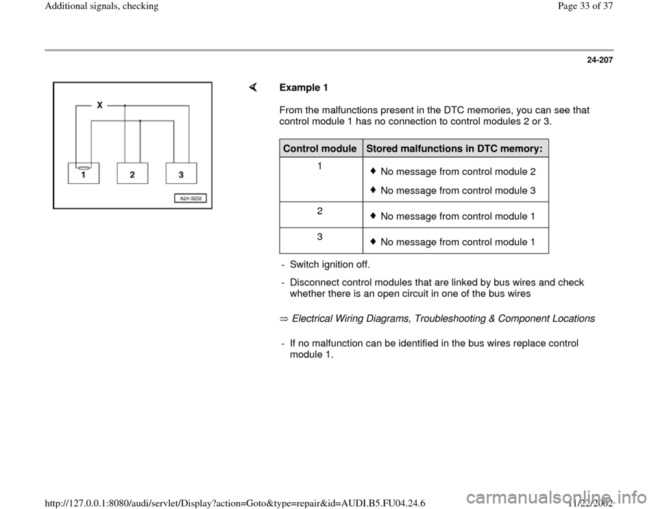
Example 1
From the malfunctions present in the DTC memories, you can see that
control module 1 has no connection to control modules 2 or 3.
Electrical Wiring Diagrams, Troubleshooting & Component Locations Control module
Stored malfunctions in DTC memory:
1
No message from control module 2No message from control module 3
2 No message from control module 1
3 No message from control module 1
- Switch ignition off.
- Disconnect control modules that are linked by bus wires and check
whether there is an open circuit in one of the bus wires - If no malfunction can be identified in the bus wires replace control
module 1.
Pa
ge 33 of 37 Additional si
gnals, checkin
g
11/22/2002 htt
p://127.0.0.1:8080/audi/servlet/Dis
play?action=Goto&t
yp
e=re
pair&id=AUDI.B5.FU04.24.6