wiring AUDI A4 1998 B5 / 1.G APB Engine Ignition System Checking
[x] Cancel search | Manufacturer: AUDI, Model Year: 1998, Model line: A4, Model: AUDI A4 1998 B5 / 1.GPages: 64, PDF Size: 0.37 MB
Page 24 of 64
28-22
Notes:
If the specification is not attained:
If the specification is attained:
If the specification is not attained:
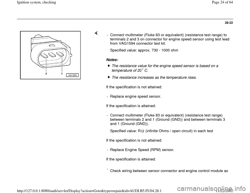
If the specification is attained: - Connect multimeter (Fluke 83 or equivalent) (resistance test range) to
terminals 2 and 3 on connector for engine speed sensor using test lead
from VAG1594 connector test kit.
Specified value: approx. 730 - 1000 ohm
The resistance value for the engine speed sensor is based on a
temperature of 20 C. The resistance increases as the temperature rises.
- Replace engine speed sensor.
- Connect multimeter (Fluke 83 or equivalent) (resistance test range)
between terminals 2 and 1 (Ground (GND)) and between terminals 3
and 1 (Ground (GND)).
Specified value: R (infinite Ohms / open circuit) in each test
- Replace Engine Speed (RPM) sensor.
-
Check wiring between sensor connector and engine control module as
Pa
ge 24 of 64 I
gnition s
ystem, checkin
g
11/22/2002 htt
p://127.0.0.1:8080/audi/servlet/Dis
play?action=Goto&t
yp
e=re
pair&id=AUDI.B5.FU04.28.1
Page 26 of 64
28-23
- Connect VAG1598/31 test box to wiring harness
for engine control module. Do not connect to the
engine control module itself Page 24
-20
.
Specified value: max. 1 .
Specified value: max. 1 .
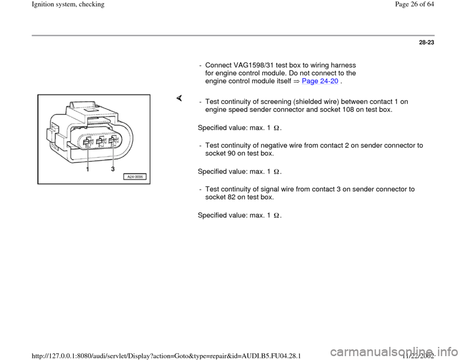
Specified value: max. 1 . - Test continuity of screening (shielded wire) between contact 1 on
engine speed sender connector and socket 108 on test box. - Test continuity of negative wire from contact 2 on sender connector to
socket 90 on test box. - Test continuity of signal wire from contact 3 on sender connector to
socket 82 on test box.
Pa
ge 26 of 64 I
gnition s
ystem, checkin
g
11/22/2002 htt
p://127.0.0.1:8080/audi/servlet/Dis
play?action=Goto&t
yp
e=re
pair&id=AUDI.B5.FU04.28.1
Page 27 of 64
28-24
If the values are not as specified:
- Rectify short or open circuit in wiring between
sender connector and control module connector.
Terminal on sensor
connector
Terminal on control
module connector
1
2
3 108
90
82
- If no open circuits or short circuits are identified,
replace Engine Control Module (ECM) Page
24
-24
.
Pa
ge 27 of 64 I
gnition s
ystem, checkin
g
11/22/2002 htt
p://127.0.0.1:8080/audi/servlet/Dis
play?action=Goto&t
yp
e=re
pair&id=AUDI.B5.FU04.28.1
Page 33 of 64
28-30
If the value does match the specification:
- Connect test box VAG1598/31 to wiring harness
for engine control module. Do not connect to the
engine control module itself. Page 24
-20
.
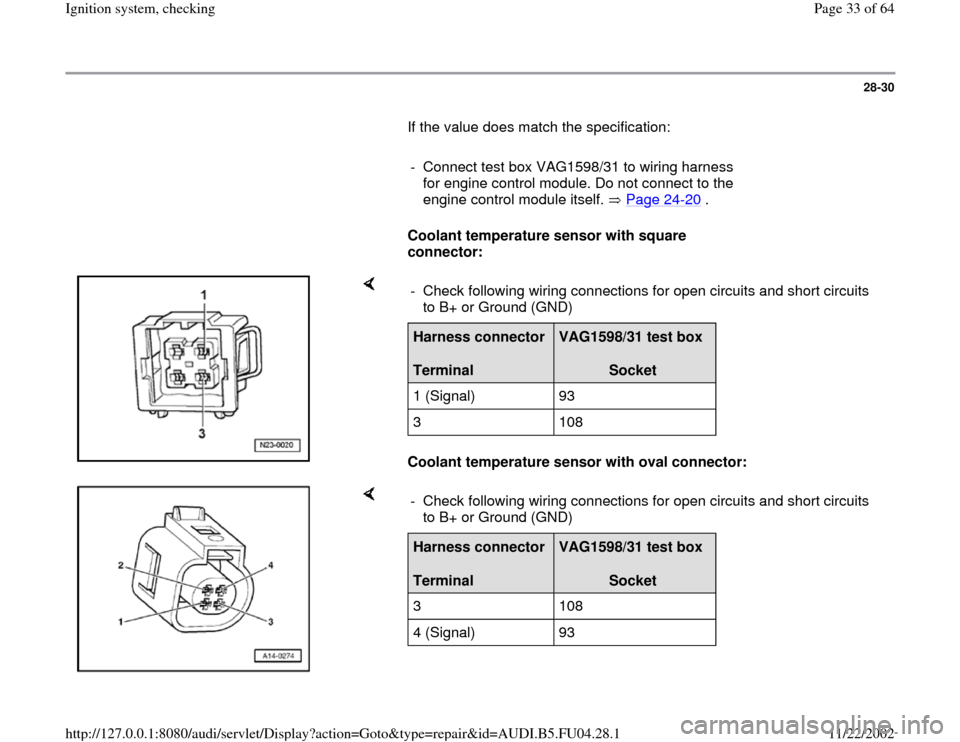
Coolant temperature sensor with square
connector:
Coolant temperature sensor with oval connector: - Check following wiring connections for open circuits and short circuits
to B+ or Ground (GND) Harness connector
Terminal
VAG1598/31 test box
Socket
1 (Signal) 93
3 108
- Check following wiring connections for open circuits and short circuits
to B+ or Ground (GND) Harness connector
Terminal
VAG1598/31 test box
Socket
3 108
4 (Signal) 93
Pa
ge 33 of 64 I
gnition s
ystem, checkin
g
11/22/2002 htt
p://127.0.0.1:8080/audi/servlet/Dis
play?action=Goto&t
yp
e=re
pair&id=AUDI.B5.FU04.28.1
Page 34 of 64
28-31
All:
- Check wiring for short circuit to each other.
- If necessary eliminate open circuit or short
circuit.
If no malfunction is identified in the wiring:
- Replace Engine Control Module (ECM) Page
24
-24
.
Pa
ge 34 of 64 I
gnition s
ystem, checkin
g
11/22/2002 htt
p://127.0.0.1:8080/audi/servlet/Dis
play?action=Goto&t
yp
e=re
pair&id=AUDI.B5.FU04.28.1
Page 35 of 64
28-32
Control module voltage supply,
checking
Test requirements:
Fuse for Engine Control Module (ECM) OK
Electrical Wiring Diagrams, Troubleshooting &
Component Locations
Battery voltage at least 11 V
Generator OK
- Connect test box VAG1598/31 to wiring harness
for engine control module. Do not connect to the
engine control module itself. Page 24
-20
.
- Switch ignition on.
Note:
The B+ voltage supply for the engine control
module comes via terminal 3 (terminal 15) and
terminal 62 (terminal 30).
Pa
ge 35 of 64 I
gnition s
ystem, checkin
g
11/22/2002 htt
p://127.0.0.1:8080/audi/servlet/Dis
play?action=Goto&t
yp
e=re
pair&id=AUDI.B5.FU04.28.1
Page 37 of 64
28-33
- Connect hand-held multimeter VAG1526
(voltage measurement range) to the following
contacts on the test box:
Contact
Specification
3 + 2 approx.
battery voltage
3 + 1 approx.
battery voltage
62 + 2 approx.
battery voltage
If the specifications are not obtained:
- Check wiring.
Electrical Wiring Diagrams, Troubleshooting &
Component Locations
Pa
ge 37 of 64 I
gnition s
ystem, checkin
g
11/22/2002 htt
p://127.0.0.1:8080/audi/servlet/Dis
play?action=Goto&t
yp
e=re
pair&id=AUDI.B5.FU04.28.1
Page 46 of 64
28-41
Knock Sensor (KS) 1 -G61 and Knock
Sensor (KS) 2 -G66, checking
Notes:
It is not possible to carry out an electrical test of
the knock sensors themselves.
To ensure that the knock sensors function
properly it is important to keep exactly to the
specified tightening torque of 20 Nm (15 ft lb)
Use only gold-plated terminals when repairing
the terminals in the plug connectors for the
knock sensors.
Check for corrosion in connection between
knock sensor and wiring harness.
Checking knock sensors
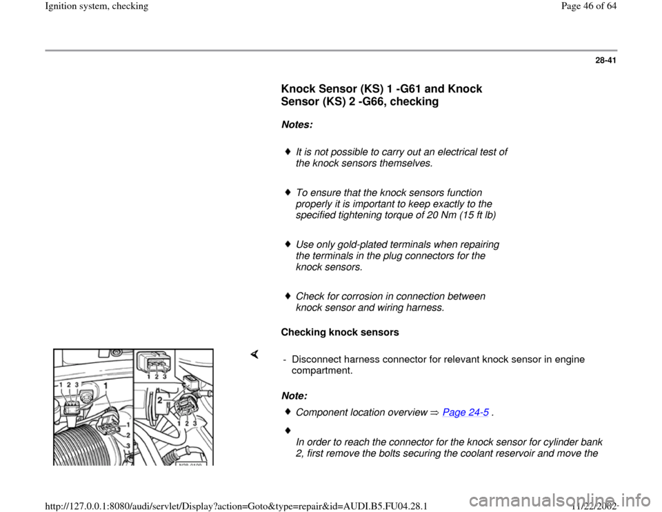
Note: - Disconnect harness connector for relevant knock sensor in engine
compartment.
Component location overview Page 24
-5 .
In order to reach the connector for the knock sensor for cylinder bank
2, first remove the bolts securing the coolant reservoir and move the
Pa
ge 46 of 64 I
gnition s
ystem, checkin
g
11/22/2002 htt
p://127.0.0.1:8080/audi/servlet/Dis
play?action=Goto&t
yp
e=re
pair&id=AUDI.B5.FU04.28.1
Page 48 of 64

28-42
If there is a connection between the terminals.
Notes:
If there is no short circuit
Checking wiring between knock sensors and engine control module - Check for short circuits between all three terminals in knock sensor
connector (terminals 1 + 2, 1 + 3 and 2 + 3).
Specified value: There must be no contact between the wires (infinite
). - Replace knock sensor.
In order to reach the knock sensors, first remove the air duct Page 24
-43
.
Use special tool 3247 to remove the knock sensors.
- Check wiring for knock sensors.
- Connect VAG1598/31 test box to wiring harness for engine control
module. Do not connect to the engine control module itself Page 24
-
20
.
Pa
ge 48 of 64 I
gnition s
ystem, checkin
g
11/22/2002 htt
p://127.0.0.1:8080/audi/servlet/Dis
play?action=Goto&t
yp
e=re
pair&id=AUDI.B5.FU04.28.1
Page 49 of 64

28-43
- Check wiring connection from relevant sensor connector to...
- ....Engine Control Module (ECM) for open circuit and/or short to B+ or
Ground (GND).
Pa
ge 49 of 64 I
gnition s
ystem, checkin
g
11/22/2002 htt
p://127.0.0.1:8080/audi/servlet/Dis
play?action=Goto&t
yp
e=re
pair&id=AUDI.B5.FU04.28.1