wiring diagram AUDI A4 1998 B5 / 1.G APB Engine Ignition System Checking
[x] Cancel search | Manufacturer: AUDI, Model Year: 1998, Model line: A4, Model: AUDI A4 1998 B5 / 1.GPages: 64, PDF Size: 0.37 MB
Page 9 of 64
28-8
If malfunction remains at the same cylinder.
- Disconnect harness connector from ignition
coil.
Electrical Wiring Diagrams, Troubleshooting & Component Locations
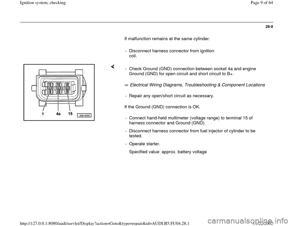
If the Ground (GND) connection is OK. - Check Ground (GND) connection between socket 4a and engine
Ground (GND) for open circuit and short circuit to B+. - Repair any open/short circuit as necessary.
- Connect hand-held multimeter (voltage range) to terminal 15 of
harness connector and Ground (GND).
- Disconnect harness connector from fuel injector of cylinder to be
tested.
- Operate starter.
Specified value: approx. battery voltage
Pa
ge 9 of 64 I
gnition s
ystem, checkin
g
11/22/2002 htt
p://127.0.0.1:8080/audi/servlet/Dis
play?action=Goto&t
yp
e=re
pair&id=AUDI.B5.FU04.28.1
Page 10 of 64
28-9
If the specification is not obtained:
- Check wiring.
Electrical Wiring Diagrams, Troubleshooting &
Component Locations If the specification is obtained:
- Disconnect 3-pin harness connectors on power
output stages for ignition coils; component
locations overview Page 24
-5 .
- Then connect diode test lamp to 3-pin
connectors for both output stages.
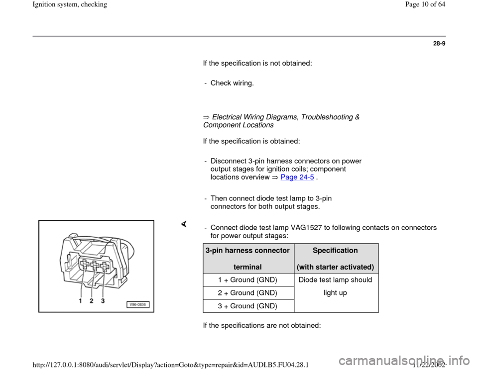
If the specifications are not obtained: - Connect diode test lamp VAG1527 to following contacts on connectors
for power output stages: 3-pin harness connector
terminal
Specification
(with starter activated)
1 + Ground (GND) Diode test lamp should
2 + Ground (GND) light up
3 + Ground (GND)
Pa
ge 10 of 64 I
gnition s
ystem, checkin
g
11/22/2002 htt
p://127.0.0.1:8080/audi/servlet/Dis
play?action=Goto&t
yp
e=re
pair&id=AUDI.B5.FU04.28.1
Page 18 of 64
28-16
- If diode test lamp does not light up, test for open
circuit in wiring using wiring diagram.
Electrical Wiring Diagrams, Troubleshooting &
Component Locations
If the diode test lamp lights up:
- Replace power output stage.
Note:
Before installing new power output stage coat
metal side with heat paste (part no. G 052 170
A1). The heat paste is used to prevent corrosion
between the power output stage and the
fastening point, it is also used to transfer heat
from the power output stage.
CAUTION!
Part numbers are only for reference, always
check with your parts department for latest
information.
Pa
ge 18 of 64 I
gnition s
ystem, checkin
g
11/22/2002 htt
p://127.0.0.1:8080/audi/servlet/Dis
play?action=Goto&t
yp
e=re
pair&id=AUDI.B5.FU04.28.1
Page 21 of 64
28-19
Checking wiring:
- Switch ignition off.
- Connect test box VAG1598/31 to wiring harness
for engine control module. Do not connect to the
engine control module itself. Page 24
-20
.
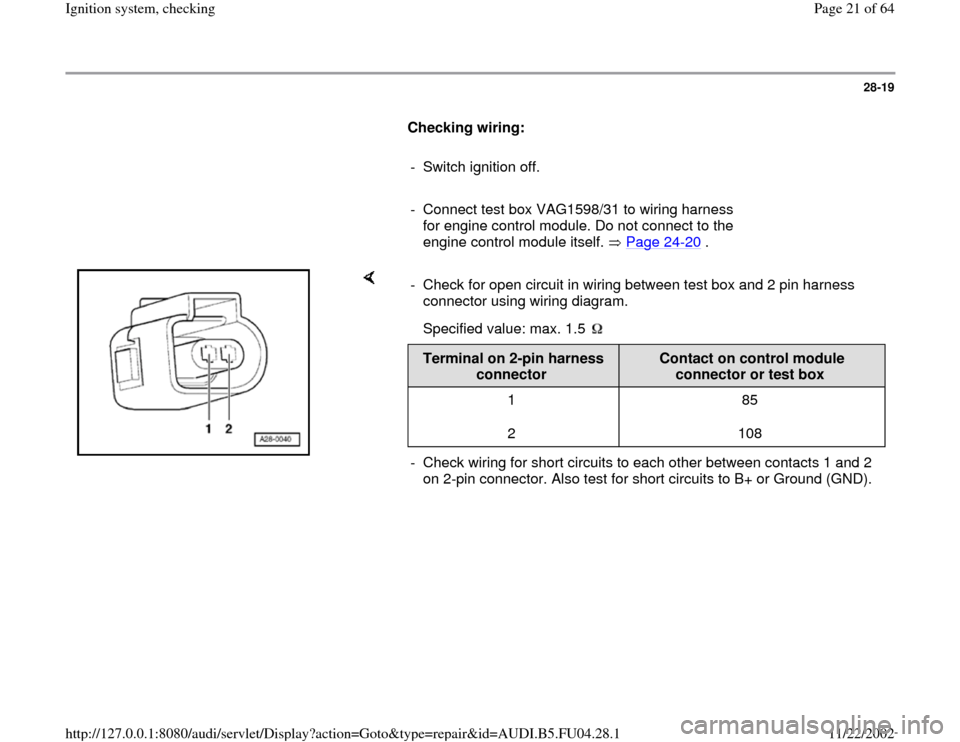
- Check for open circuit in wiring between test box and 2 pin harness
connector using wiring diagram.
Specified value: max. 1.5
Terminal on 2-pin harness
connector
Contact on control module
connector or test box
1
2 85
108
- Check wiring for short circuits to each other between contacts 1 and 2
on 2-pin connector. Also test for short circuits to B+ or Ground (GND).
Pa
ge 21 of 64 I
gnition s
ystem, checkin
g
11/22/2002 htt
p://127.0.0.1:8080/audi/servlet/Dis
play?action=Goto&t
yp
e=re
pair&id=AUDI.B5.FU04.28.1
Page 35 of 64
28-32
Control module voltage supply,
checking
Test requirements:
Fuse for Engine Control Module (ECM) OK
Electrical Wiring Diagrams, Troubleshooting &
Component Locations
Battery voltage at least 11 V
Generator OK
- Connect test box VAG1598/31 to wiring harness
for engine control module. Do not connect to the
engine control module itself. Page 24
-20
.
- Switch ignition on.
Note:
The B+ voltage supply for the engine control
module comes via terminal 3 (terminal 15) and
terminal 62 (terminal 30).
Pa
ge 35 of 64 I
gnition s
ystem, checkin
g
11/22/2002 htt
p://127.0.0.1:8080/audi/servlet/Dis
play?action=Goto&t
yp
e=re
pair&id=AUDI.B5.FU04.28.1
Page 37 of 64
28-33
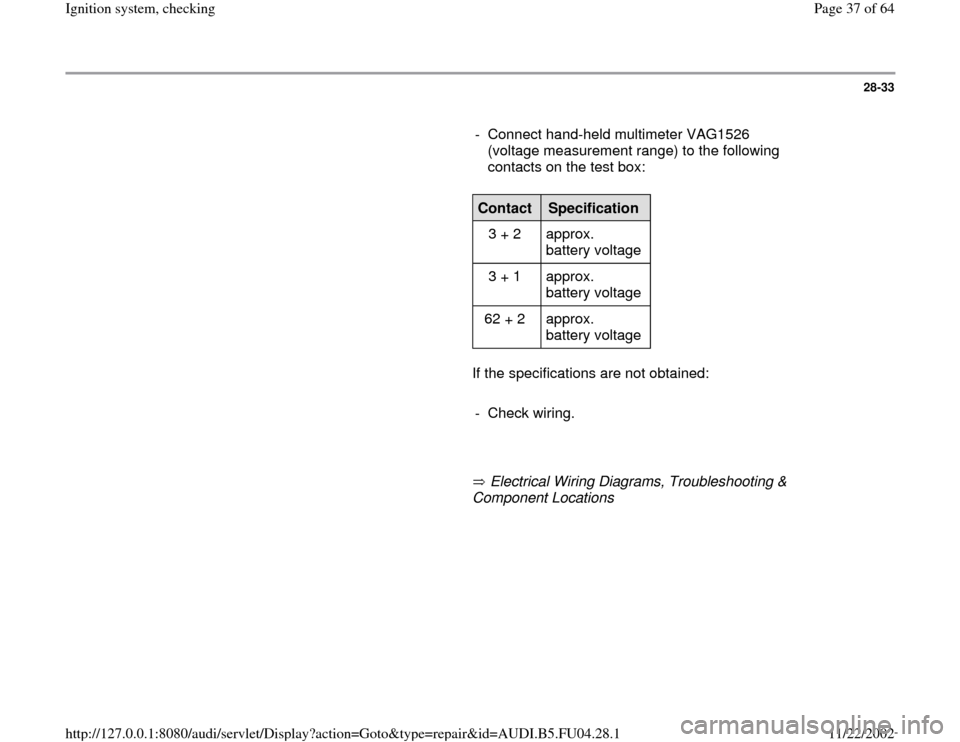
- Connect hand-held multimeter VAG1526
(voltage measurement range) to the following
contacts on the test box:
Contact
Specification
3 + 2 approx.
battery voltage
3 + 1 approx.
battery voltage
62 + 2 approx.
battery voltage
If the specifications are not obtained:
- Check wiring.
Electrical Wiring Diagrams, Troubleshooting &
Component Locations
Pa
ge 37 of 64 I
gnition s
ystem, checkin
g
11/22/2002 htt
p://127.0.0.1:8080/audi/servlet/Dis
play?action=Goto&t
yp
e=re
pair&id=AUDI.B5.FU04.28.1