light AUDI A4 1998 B5 / 1.G APB Engine Motronic Multiport Fuel Injection System Servising Workshop Manual
[x] Cancel search | Manufacturer: AUDI, Model Year: 1998, Model line: A4, Model: AUDI A4 1998 B5 / 1.GPages: 90, PDF Size: 0.84 MB
Page 7 of 90
24-5
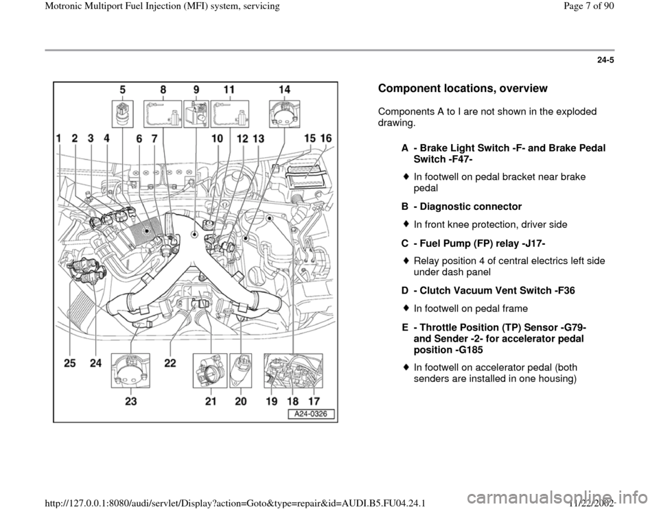
Component locations, overview
Components A to I are not shown in the exploded
drawing.
A - Brake Light Switch -F- and Brake Pedal
Switch -F47-
In footwell on pedal bracket near brake
pedal
B - Diagnostic connectorIn front knee protection, driver side
C - Fuel Pump (FP) relay -J17-Relay position 4 of central electrics left side
under dash panel
D - Clutch Vacuum Vent Switch -F36In footwell on pedal frame
E - Throttle Position (TP) Sensor -G79-
and Sender -2- for accelerator pedal
position -G185 In footwell on accelerator pedal (both
senders are installed in one housing)
Pa
ge 7 of 90 Motronic Multi
port Fuel In
jection
(MFI
) system, servicin
g
11/22/2002 htt
p://127.0.0.1:8080/audi/servlet/Dis
play?action=Goto&t
yp
e=re
pair&id=AUDI.B5.FU04.24.1
Page 8 of 90
24-6
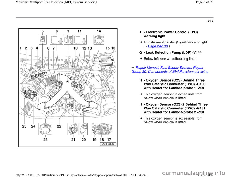
Repair Manual, Fuel Supply System, Repair
Group 20, Components of EVAP system servicing
F - Electronic Power Control (EPC)
warning light
In instrument cluster (Significance of light
Page 24
-139
)
G - Leak Detection Pump (LDP) -V144
Below left rear wheelhousing liner
H - Oxygen Sensor (O2S) Behind Three
Way Catalytic Converter (TWC) -G130
with Heater for Lambda-probe 1 -Z29
This oxygen sensor is accessible from
below when vehicle is lifted
I - Oxygen Sensor (O2S) 2 Behind Three
Way Catalytic Converter (TWC) -G131
with Heater for Lambda-probe 2 -Z30 This oxygen sensor is accessible from
below when vehicle is lifted
Pa
ge 8 of 90 Motronic Multi
port Fuel In
jection
(MFI
) system, servicin
g
11/22/2002 htt
p://127.0.0.1:8080/audi/servlet/Dis
play?action=Goto&t
yp
e=re
pair&id=AUDI.B5.FU04.24.1
Page 48 of 90
24-41
- Switch ignition on. The diode test lamp should
light up.
- If diode test lamp does not light up, test for open
circuits in wiring between contact 1 and fuse for
injectors. If necessary, rectify open circuit.
Electrical Wiring Diagrams, Troubleshooting &
Component Locations
- If diode test lamp lights up, test activation of
injectors.
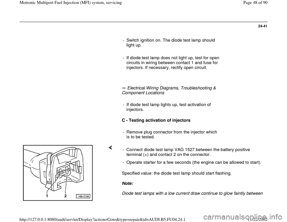
C - Testing activation of injectors
- Remove plug connector from the injector which
is to be tested.
Specified value: the diode test lamp should start flashing.
Note:
Diode test lamps with a low current draw continue to glow faintly between - Connect diode test lamp VAG 1527 between the battery positive
terminal (+) and contact 2 on the connector.
- Operate starter for a few seconds (the engine can be allowed to start).
Pa
ge 48 of 90 Motronic Multi
port Fuel In
jection
(MFI
) system, servicin
g
11/22/2002 htt
p://127.0.0.1:8080/audi/servlet/Dis
play?action=Goto&t
yp
e=re
pair&id=AUDI.B5.FU04.24.1
Page 64 of 90
24-54
Fuel Pump (FP) relay -J17 and relay
activation, checking
Note:
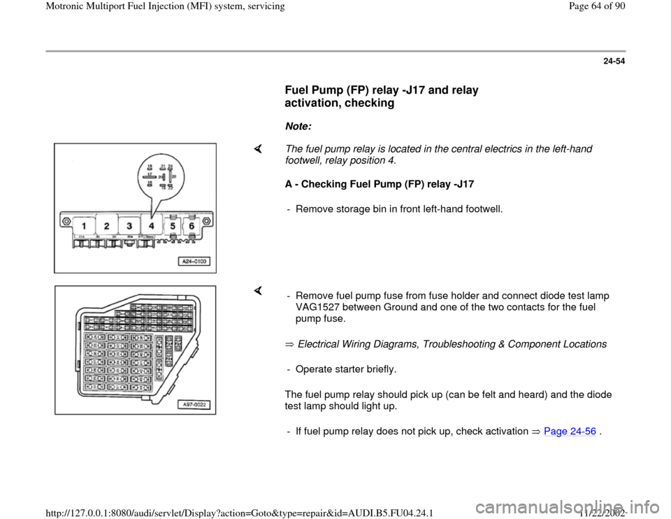
The fuel pump relay is located in the central electrics in the left-hand
footwell, relay position 4.
A - Checking Fuel Pump (FP) relay -J17
- Remove storage bin in front left-hand footwell.
Electrical Wiring Diagrams, Troubleshooting & Component Locations
The fuel pump relay should pick up (can be felt and heard) and the diode
test lamp should light up. - Remove fuel pump fuse from fuse holder and connect diode test lamp
VAG1527 between Ground and one of the two contacts for the fuel
pump fuse. - Operate starter briefly.
- If fuel pump relay does not pick up, check activation Page 24
-56
.
Pa
ge 64 of 90 Motronic Multi
port Fuel In
jection
(MFI
) system, servicin
g
11/22/2002 htt
p://127.0.0.1:8080/audi/servlet/Dis
play?action=Goto&t
yp
e=re
pair&id=AUDI.B5.FU04.24.1
Page 65 of 90
24-55
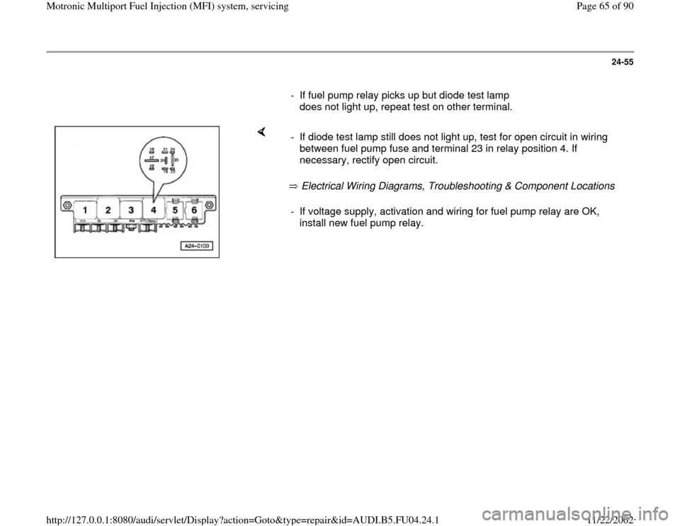
- If fuel pump relay picks up but diode test lamp
does not light up, repeat test on other terminal.
Electrical Wiring Diagrams, Troubleshooting & Component Locations - If diode test lamp still does not light up, test for open circuit in wiring
between fuel pump fuse and terminal 23 in relay position 4. If
necessary, rectify open circuit. - If voltage supply, activation and wiring for fuel pump relay are OK,
install new fuel pump relay.
Pa
ge 65 of 90 Motronic Multi
port Fuel In
jection
(MFI
) system, servicin
g
11/22/2002 htt
p://127.0.0.1:8080/audi/servlet/Dis
play?action=Goto&t
yp
e=re
pair&id=AUDI.B5.FU04.24.1
Page 67 of 90
24-57
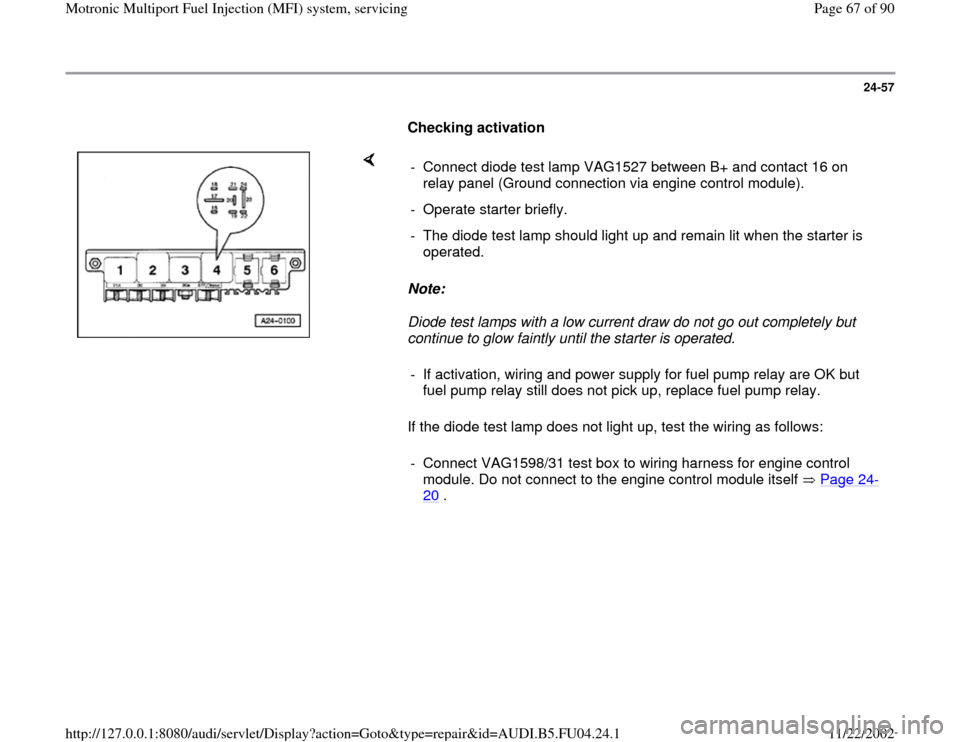
Checking activation
Note:
Diode test lamps with a low current draw do not go out completely but
continue to glow faintly until the starter is operated.
If the diode test lamp does not light up, test the wiring as follows: - Connect diode test lamp VAG1527 between B+ and contact 16 on
relay panel (Ground connection via engine control module).
- Operate starter briefly.
- The diode test lamp should light up and remain lit when the starter is
operated.
- If activation, wiring and power supply for fuel pump relay are OK but
fuel pump relay still does not pick up, replace fuel pump relay.
- Connect VAG1598/31 test box to wiring harness for engine control
module. Do not connect to the engine control module itself Page 24
-
20
.
Pa
ge 67 of 90 Motronic Multi
port Fuel In
jection
(MFI
) system, servicin
g
11/22/2002 htt
p://127.0.0.1:8080/audi/servlet/Dis
play?action=Goto&t
yp
e=re
pair&id=AUDI.B5.FU04.24.1
Page 68 of 90
24-58
- Connect hand-held multimeter between contact
16 on relay panel and socket 65 on the test box,
then test wiring for open circuits.
- Rectify open circuit if necessary.
Electrical Wiring Diagrams, Troubleshooting &
Component Locations
- If there is no open circuit and the diode test lamp
still does not light up:
- Replace Engine Control Module (ECM) Page
24
-24
.
- Reinstall fuel pump fuse.
Pa
ge 68 of 90 Motronic Multi
port Fuel In
jection
(MFI
) system, servicin
g
11/22/2002 htt
p://127.0.0.1:8080/audi/servlet/Dis
play?action=Goto&t
yp
e=re
pair&id=AUDI.B5.FU04.24.1