sensor AUDI A4 1998 B5 / 1.G APB Engine Motronic Syst
[x] Cancel search | Manufacturer: AUDI, Model Year: 1998, Model line: A4, Model: AUDI A4 1998 B5 / 1.GPages: 166, PDF Size: 0.53 MB
Page 87 of 166
01-72
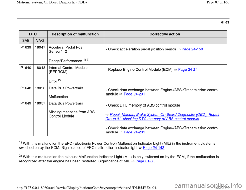
DTC
Description of malfunction
Corrective action
SAE
VAG
P1639 18047 Accelera. Pedal Pos.
Sensor1+2
Range/Performance
1) 3)
- Check acceleration pedal position sensor Page 24
-159
P1640 18048 Internal Control Module
(EEPROM)
Error
2) - Replace Engine Control Module (ECM) Page 24
-24
.
P1648 18056 Data Bus Powertrain
Malfunction - Check data exchange between Engine-/ABS-/Transmission control
module Page 24
-201
P1649 18057 Data Bus Powertrain
Missing message from ABS
Control Module Repair Manual, Brake System On Board Diagnostic (OBD), Repair
Group 01, checking DTC memory of ABS control module
- Check DTC memory of ABS control module
- Check data exchange between Engine-/ABS-/Transmission control
module Page 24
-201
1) With this malfunction the EPC (Electronic Power Control) Malfunction Indicator Light (MIL) in the instrument cluster is
switched on by the ECM. Significance of EPC malfunction indicator light Page 24
-142
.
2) With this malfunction the exhaust Malfunction Indicator Light (MIL) is only switched on by the ECM, if the malfunction is
recognized after the engine has been restarted. Significance of MIL Page 01
-3 .
Pa
ge 87 of 166 Motronic s
ystem, On Board Dia
gnostic
(OBD
)
11/22/2002 htt
p://127.0.0.1:8080/audi/servlet/Dis
play?action=Goto&t
yp
e=re
pair&id=AUDI.B5.FU04.01.1
Page 91 of 166
01-74
DTC
Description of malfunction
Corrective action
SAE
VAG
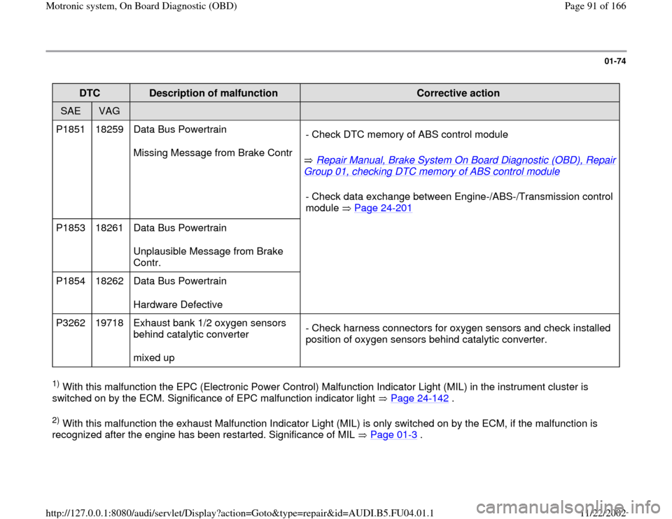
P1851 18259 Data Bus Powertrain
Missing Message from Brake Contr
Repair Manual, Brake System On Board Diagnostic (OBD), Repair
Group 01, checking DTC memory of ABS control module
- Check DTC memory of ABS control module
- Check data exchange between Engine-/ABS-
/Transmission control
module Page 24
-201
P1853 18261 Data Bus Powertrain
Unplausible Message from Brake
Contr.
P1854 18262 Data Bus Powertrain
Hardware Defective
P3262 19718 Exhaust bank 1/2 oxygen sensors
behind catalytic converter
mixed up - Check harness connectors for oxygen sensors and check installed
position of oxygen sensors behind catalytic converter. 1) With this malfunction the EPC (Electronic Power Control) Malfunction Indicator Light (MIL) in the instrument cluster is
switched on by the ECM. Significance of EPC malfunction indicator light Page 24
-142
.
2) With this malfunction the exhaust Malfunction Indicator Light (MIL) is only switched on by the ECM, if the malfunction is
recognized after the engine has been restarted. Significance of MIL Page 01
-3 .
Pa
ge 91 of 166 Motronic s
ystem, On Board Dia
gnostic
(OBD
)
11/22/2002 htt
p://127.0.0.1:8080/audi/servlet/Dis
play?action=Goto&t
yp
e=re
pair&id=AUDI.B5.FU04.01.1
Page 106 of 166
01-88
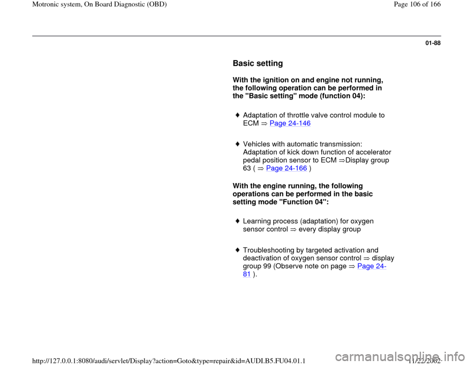
Basic setting
With the ignition on and engine not running,
the following operation can be performed in
the "Basic setting" mode (function 04):
Adaptation of throttle valve control module to
ECM Page 24
-146
Vehicles with automatic transmission:
Adaptation of kick down function of accelerator
pedal position sensor to ECM Display group
63 ( Page 24
-166
)
With the engine running, the following
operations can be performed in the basic
setting mode "Function 04":
Learning process (adaptation) for oxygen
sensor control every display group
Troubleshooting by targeted activation and
deactivation of oxygen sensor control display
group 99 (Observe note on page Page 24
-
81
).
Pa
ge 106 of 166 Motronic s
ystem, On Board Dia
gnostic
(OBD
)
11/22/2002 htt
p://127.0.0.1:8080/audi/servlet/Dis
play?action=Goto&t
yp
e=re
pair&id=AUDI.B5.FU04.01.1
Page 124 of 166
01-103
X
X
X
X
X
X
X
X
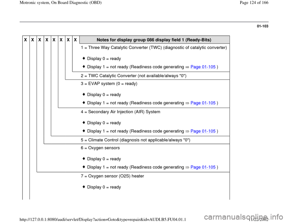
Notes for display group 086 display field 1 (Ready-Bits)
1 = Three Way Catalytic Converter (TWC) (diagnostic of catalytic converter)
Display 0 = ready
Display 1 = not ready (Readiness code generating Page 01
-105
)
2 = TWC Catalytic Converter (not available/always "0")
3 = EVAP system (0 = ready)
Display 0 = ready
Display 1 = not ready (Readiness code generating Page 01
-105
)
4 = Secondary Air Injection (AIR) System
Display 0 = ready
Display 1 = not ready (Readiness code generating Page 01
-105
)
5 = Climate Control (diagnosis not applicable/always "0")
6 = Oxygen sensors
Display 0 = ready
Display 1 = not ready (Readiness code generating Page 01
-105
)
7 = Oxygen sensor (O2S) heater
Display 0 = ready
Pa
ge 124 of 166 Motronic s
ystem, On Board Dia
gnostic
(OBD
)
11/22/2002 htt
p://127.0.0.1:8080/audi/servlet/Dis
play?action=Goto&t
yp
e=re
pair&id=AUDI.B5.FU04.01.1
Page 131 of 166

01-109
Display fields
1 2 3 4
Display group 060: Adaptation of throttle valve control module
Display xx % xx %
x
---
Indicated Throttle
valve angle
(angle
sensor 1) Throttle
valve angle
(angle
sensor 2) Adaptation step counter
Adaptation condition
Work area 0 - 100 % 0 - 100 %
0 - 8
ADP. runs
ADP. OK
ADP. ERROR
Specified
value 3 - 93 % 97 - 3 %
8
ADP. OK
Note:
During adaptation, adaptation step counter
must reach the number 8. (Some numbers
may be skipped). If "ADP. ERROR." is displayed:
Check DTC memory Page
01
-15
.
If specified value is not
obtained: Note, Page Page
24
-152
.
Note for display field 3:
During adaptation different digits are displayed in display field 3, which indicate the particular adaptation condition. It is not
important what the adaptation step counter (display field 3) displays during adaptation, rather that display field 4 displays the
Pa
ge 131 of 166 Motronic s
ystem, On Board Dia
gnostic
(OBD
)
11/22/2002 htt
p://127.0.0.1:8080/audi/servlet/Dis
play?action=Goto&t
yp
e=re
pair&id=AUDI.B5.FU04.01.1
Page 135 of 166

01-111
Display fields
1 2 3 4
Display group 070: Diagnostic of EVAP canister purge regulator valve
Display xx % xx.x % xx %
Test ON
Indicated EVAP valve duty
cycle during
diagnosis Oxygen sensor
control deviation
during diagnosis Relative
Ground via
EVAP valve Diagnostic condition
Work
Range min.: 0 %
max.: 100 % min.: -25.0 %
max.: 25.0 %
Test OFF
Test ON
EVAP OK
EVAP n.OK
Abort
Specified
value xx % -5.0 to 4.0 %
xx - xx %
1)
EVAP OK
Note:
If "EVAP n. OK" is displayed: Check DTC
memory Page 01
-15
. Check EVAP canister
purge regulator valve -N80 Page 24
-134
1) A display appears only, if the diagnostic result occurred via deviation from the Idle Air Control (IAC) in a specified tolerance
range and not from deviation from the oxygen sensor control (e.g.: oxygen sensor 1 from EVAP canister). Display field 3 is
only indicated if there is a deviation.
Pa
ge 135 of 166 Motronic s
ystem, On Board Dia
gnostic
(OBD
)
11/22/2002 htt
p://127.0.0.1:8080/audi/servlet/Dis
play?action=Goto&t
yp
e=re
pair&id=AUDI.B5.FU04.01.1
Page 139 of 166

01-115
If specified value in display field "System OK" is
reached:
- Press -C- button.
Work step 6: Diagnosis of fuel supply system
Test requirements
Engine at idle
Oxygen sensor control active
System in Basic S
ystem
Q
Input display group number XXX
When indicated on display
- Press buttons -1-, -0- and -7- to select display group number 107 and
confirm with -Q- button.
System in Basic Setting 107
1
2
3
4
When indicated on display
Note:
If display "Test ON" does not appear in the display field, switch the engine
off and restart afterward and repeat work step 6. (Diagnostic of fuel supply
system)
After the engine has been started it might be necessary to select "Address
word 01" and initiate the function "04 Basic Setting" again. - Check specified values in display field 4.
Pa
ge 139 of 166 Motronic s
ystem, On Board Dia
gnostic
(OBD
)
11/22/2002 htt
p://127.0.0.1:8080/audi/servlet/Dis
play?action=Goto&t
yp
e=re
pair&id=AUDI.B5.FU04.01.1
Page 140 of 166

01-116
Display fields
1 2 3 4
Display group 107: Diagnostic of fuel supply
Display xxx /RPM x.x % x.x %
Test ON
Indicated Engine speed
(actual) Oxygen sensor control
average value (Bank 1) Oxygen sensor control
average value (Bank 2) Diagnostic condition
Work
range min.: 750 /RPM
max.:
6800 /RPM min.: -25.0 %
max.: 25.0 % min.: -25.0 %
max.: 25.0 % Test OFF
Test ON
Syst. OK
Syst. n OK
Value 750 - 850/RPM -18.0 % to 12.0 % -18.0 % to 12.0 % Syst. OK
Note
If "Syst. n OK" appears, check
DTC memory Page 01
-15
.
Pa
ge 140 of 166 Motronic s
ystem, On Board Dia
gnostic
(OBD
)
11/22/2002 htt
p://127.0.0.1:8080/audi/servlet/Dis
play?action=Goto&t
yp
e=re
pair&id=AUDI.B5.FU04.01.1
Page 141 of 166

01-117
If specified value in display "System OK" is
reached:
- Press -C- button.
Work step 7: Diagnosis of oxygen sensor
heater System in Basic Setting
Q
Input displa
y group number XXX
When indicated on display
- Press buttons -0-, -4- and -1- to select display group number 041 and
confirm with -Q- button.
System in Basic Setting 41
1
2
3
4
When indicated on display
Note:
Increasing engine speed accelerates the obtaining of specified values. - Check specified value in display field 1 and 3:
Pa
ge 141 of 166 Motronic s
ystem, On Board Dia
gnostic
(OBD
)
11/22/2002 htt
p://127.0.0.1:8080/audi/servlet/Dis
play?action=Goto&t
yp
e=re
pair&id=AUDI.B5.FU04.01.1
Page 142 of 166
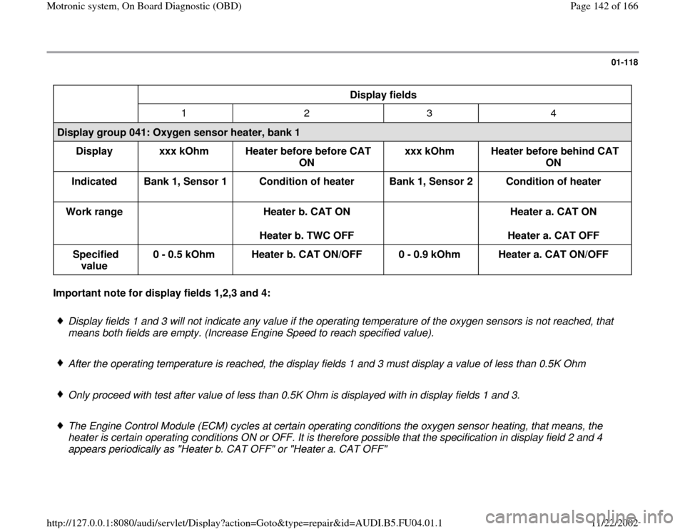
01-118
Display fields
1 2 3 4
Display group 041: Oxygen sensor heater, bank 1
Display
xxx kOhm
Heater before before CAT
ON xxx kOhm
Heater before behind CAT
ON
Indicated
Bank 1, Sensor 1
Condition of heater
Bank 1, Sensor 2
Condition of heater
Work range
Heater b. CAT ON
Heater b. TWC OFF
Heater a. CAT ON
Heater a. CAT OFF
Specified
value 0 - 0.5 kOhm
Heater b. CAT ON/OFF
0 - 0.9 kOhm
Heater a. CAT ON/OFF Important note for display fields 1,2,3 and 4:
Display fields 1 and 3 will not indicate any value if the operating temperature of the oxygen sensors is not reached, that
means both fields are empty. (Increase Engine Speed to reach specified value).
After the operating temperature is reached, the display fields 1 and 3 must display a value of less than 0.5K Ohm
Only proceed with test after value of less than 0.5K Ohm is displayed with in display fields 1 and 3.
The Engine Control Module (ECM) cycles at certain operating conditions the oxygen sensor heating, that means, the
heater is certain operating conditions ON or OFF. It is therefore possible that the specification in display field 2 and 4
appears periodically as "Heater b. CAT OFF" or "Heater a. CAT OFF"
Pa
ge 142 of 166 Motronic s
ystem, On Board Dia
gnostic
(OBD
)
11/22/2002 htt
p://127.0.0.1:8080/audi/servlet/Dis
play?action=Goto&t
yp
e=re
pair&id=AUDI.B5.FU04.01.1