oil AUDI A4 1998 B5 / 1.G APB Engine Valve Gear Service Owner's Manual
[x] Cancel search | Manufacturer: AUDI, Model Year: 1998, Model line: A4, Model: AUDI A4 1998 B5 / 1.GPages: 99, PDF Size: 1.78 MB
Page 35 of 99
15-35
Notes:
Mark the direction of rotation of the toothed belt
with chalk or felt pen before removing. A used
belt can break if it rotates in the wrong direction
when reinstalled.
The toothed belt tensioning element is oil-
damped and can therefore only be compressed
slowly by applying constant pressure.
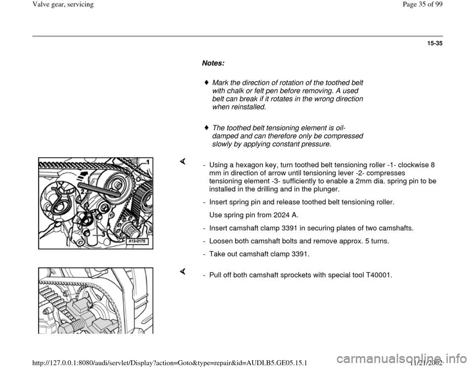
- Using a hexagon key, turn toothed belt tensioning roller -1- clockwise 8
mm in direction of arrow until tensioning lever -2- compresses
tensioning element -3- sufficiently to enable a 2mm dia. spring pin to be
installed in the drilling and in the plunger.
- Insert spring pin and release toothed belt tensioning roller.
Use spring pin from 2024 A.
- Insert camshaft clamp 3391 in securing plates of two camshafts.
- Loosen both camshaft bolts and remove approx. 5 turns.
- Take out camshaft clamp 3391.
- Pull off both camshaft sprockets with special tool T40001.
Pa
ge 35 of 99 Valve
gear, servicin
g
11/21/2002 htt
p://127.0.0.1:8080/audi/servlet/Dis
play?action=Goto&t
yp
e=re
pair&id=AUDI.B5.GE05.15.1
Page 39 of 99
15-39
Installing
Notes:
Do not allow any oil or coolant to remain in the
blind holes for the cylinder head bolts in the
cylinder block.
Replace cylinder head bolts.
Connecting vacuum hoses Page 10
-28
.
When installing a new cylinder head:
- Screw in centering pin for intake manifold.
The cylinder head supplied as a replacement
part can be used on both sides (left or right). But
a sealing cap (core plug) must be installed in the
front end of the cylinder head in each case.
- Coat outside circumference of sealing cap (core
plug) with sealant AMV 188 001 02.
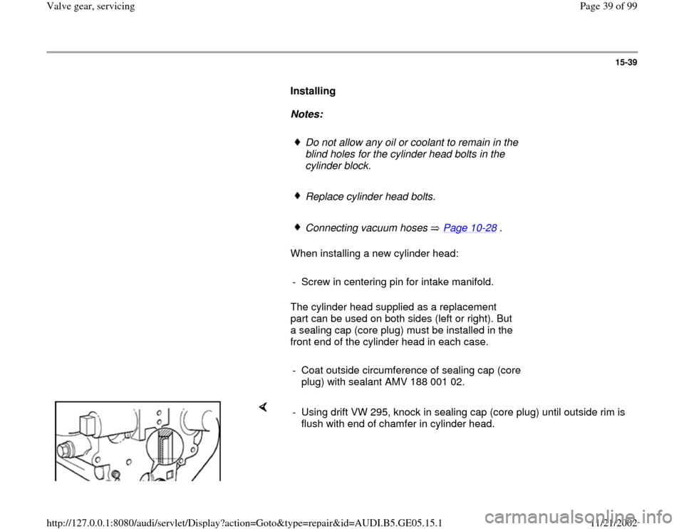
- Using drift VW 295, knock in sealing cap (core plug) until outside rim is
flush with end of chamfer in cylinder head.
Pa
ge 39 of 99 Valve
gear, servicin
g
11/21/2002 htt
p://127.0.0.1:8080/audi/servlet/Dis
play?action=Goto&t
yp
e=re
pair&id=AUDI.B5.GE05.15.1
Page 44 of 99
15-44
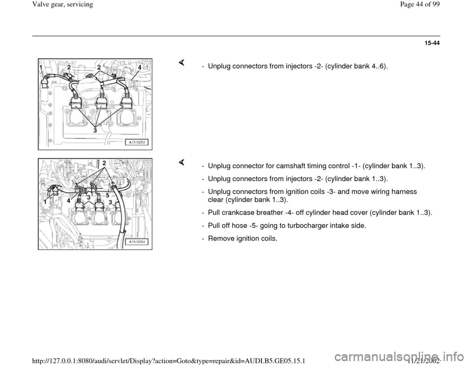
- Unplug connectors from injectors -2- (cylinder bank 4..6).
- Unplug connector for camshaft timing control -1- (cylinder bank 1..3).
- Unplug connectors from injectors -2- (cylinder bank 1..3).
- Unplug connectors from ignition coils -3- and move wiring harness
clear (cylinder bank 1..3).
- Pull crankcase breather -4- off cylinder head cover (cylinder bank 1..3).
- Pull off hose -5- going to turbocharger intake side.
- Remove ignition coils.
Pa
ge 44 of 99 Valve
gear, servicin
g
11/21/2002 htt
p://127.0.0.1:8080/audi/servlet/Dis
play?action=Goto&t
yp
e=re
pair&id=AUDI.B5.GE05.15.1
Page 49 of 99
15-49
Notes:
Mark the direction of rotation of the toothed belt
with chalk or felt pen before removing. A used
belt can break if it rotates in the wrong direction
when reinstalled.
The toothed belt tensioning element is oil-
damped and can therefore only be compressed
slowly by applying constant pressure.
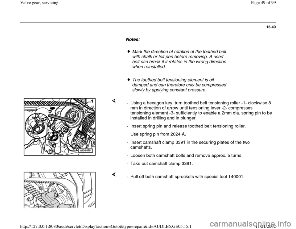
- Using a hexagon key, turn toothed belt tensioning roller -1- clockwise 8
mm in direction of arrow until tensioning lever -2- compresses
tensioning element -3- sufficiently to enable a 2mm dia. spring pin to be
installed in drilling and in plunger.
- Insert spring pin and release toothed belt tensioning roller.
Use spring pin from 2024 A.
- Insert camshaft clamp 3391 in the securing plates of the two
camshafts.
- Loosen both camshaft bolts and remove approx. 5 turns.
- Take out camshaft clamp 3391.
- Pull off both camshaft sprockets with special tool T40001.
Pa
ge 49 of 99 Valve
gear, servicin
g
11/21/2002 htt
p://127.0.0.1:8080/audi/servlet/Dis
play?action=Goto&t
yp
e=re
pair&id=AUDI.B5.GE05.15.1
Page 53 of 99
15-53
Installing
Notes:
Do not allow any oil or coolant to remain in the
blind holes for the cylinder head bolts in the
cylinder block.
Install new cylinder head bolts.
Connecting vacuum hoses Page 10
-28
.
When installing a new cylinder head:
- Screw in centering pin for intake manifold.
The cylinder head supplied as a replacement
part can be used on both sides (left or right). But
a sealing cap (core plug) must be installed in the
front end of the cylinder head in each case.
- Coat outside circumference of sealing cap (core
plug) with sealant AMV 188 001 02.
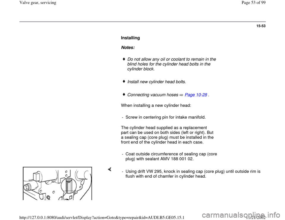
- Using drift VW 295, knock in sealing cap (core plug) until outside rim is
flush with end of chamfer in cylinder head.
Pa
ge 53 of 99 Valve
gear, servicin
g
11/21/2002 htt
p://127.0.0.1:8080/audi/servlet/Dis
play?action=Goto&t
yp
e=re
pair&id=AUDI.B5.GE05.15.1
Page 58 of 99
15-58
Compression, checking
Test requirements:
Engine oil temperature at least 30 C.
Battery fully charged.
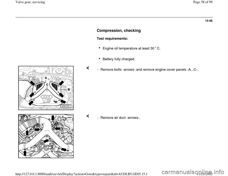
- Remove bolts -arrows- and remove engine cover panels -A...C-.
- Remove air duct -arrows-.
Pa
ge 58 of 99 Valve
gear, servicin
g
11/21/2002 htt
p://127.0.0.1:8080/audi/servlet/Dis
play?action=Goto&t
yp
e=re
pair&id=AUDI.B5.GE05.15.1
Page 63 of 99
15-63
- Pull crankcase breathers off cylinder head
covers.
- Pull plug connectors off ignition coils.
- Remove ignition coils.
- Unplug connectors from all 6 injectors.
- Disconnect 5-pin connecter at power output
stage of ignition coils.
- Open throttle fully.
- Use compression tester VAG 1381 or VAG
1763.
- Operate starter until pressure reading on tester
no longer rises.
Compression pressure values
New
Wear
limit Max. permissible difference
between cylinders
9 ... 13
bar 7 bar 3 bar
Pa
ge 63 of 99 Valve
gear, servicin
g
11/21/2002 htt
p://127.0.0.1:8080/audi/servlet/Dis
play?action=Goto&t
yp
e=re
pair&id=AUDI.B5.GE05.15.1
Page 64 of 99
15-64
Installing
Install in reverse sequence; note the following
points.
- install fuse No. 28 (for fuel pump).
- Erase Diagnostic Trouble Code (DTC)
memory.
Note:
Malfunctions will have been stored in the
memory because the connector to the Hall
sensor has been unplugged. Therefore
interrogate and erase the DTC memory after the
test.
Tightening torque
Component
Nm
Ignition coils to cylinder head 10
Spark plugs in cylinder head 30
Pa
ge 64 of 99 Valve
gear, servicin
g
11/21/2002 htt
p://127.0.0.1:8080/audi/servlet/Dis
play?action=Goto&t
yp
e=re
pair&id=AUDI.B5.GE05.15.1
Page 78 of 99
15-77
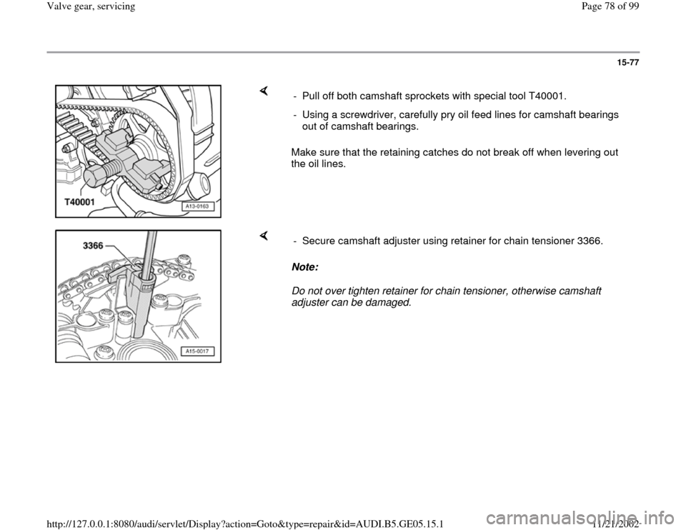
Make sure that the retaining catches do not break off when levering out
the oil lines. - Pull off both camshaft sprockets with special tool T40001.
- Using a screwdriver, carefully pry oil feed lines for camshaft bearings
out of camshaft bearings.
Note:
Do not over tighten retainer for chain tensioner, otherwise camshaft
adjuster can be damaged. - Secure camshaft adjuster using retainer for chain tensioner 3366.
Pa
ge 78 of 99 Valve
gear, servicin
g
11/21/2002 htt
p://127.0.0.1:8080/audi/servlet/Dis
play?action=Goto&t
yp
e=re
pair&id=AUDI.B5.GE05.15.1
Page 81 of 99
15-80
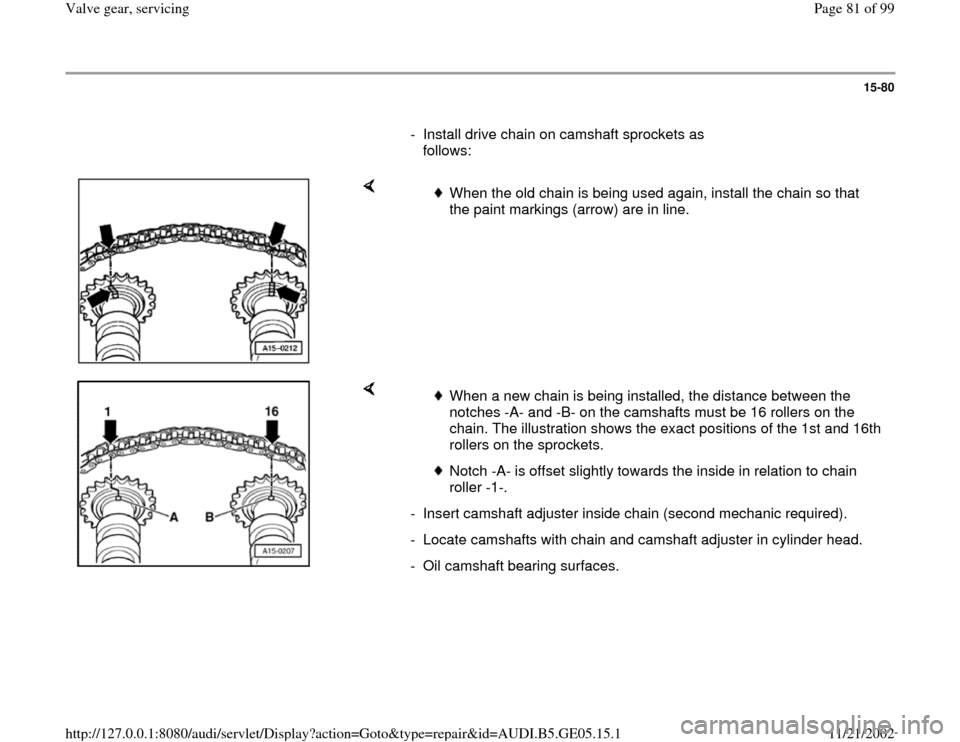
- Install drive chain on camshaft sprockets as
follows:
When the old chain is being used again, install the chain so that
the paint markings (arrow) are in line.
When a new chain is being installed, the distance between the
notches -A- and -B- on the camshafts must be 16 rollers on the
chain. The illustration shows the exact positions of the 1st and 16th
rollers on the sprockets.
Notch -A- is offset slightly towards the inside in relation to chain
roller -1-.
- Insert camshaft adjuster inside chain (second mechanic required).
- Locate camshafts with chain and camshaft adjuster in cylinder head.
- Oil camshaft bearing surfaces.
Pa
ge 81 of 99 Valve
gear, servicin
g
11/21/2002 htt
p://127.0.0.1:8080/audi/servlet/Dis
play?action=Goto&t
yp
e=re
pair&id=AUDI.B5.GE05.15.1