wiring AUDI A4 1998 B5 / 1.G APB Engine Valve Gear Service Workshop Manual
[x] Cancel search | Manufacturer: AUDI, Model Year: 1998, Model line: A4, Model: AUDI A4 1998 B5 / 1.GPages: 99, PDF Size: 1.78 MB
Page 14 of 99
15-14
Removing oil seal at Hall sensor (left cylinder
head)
Note:
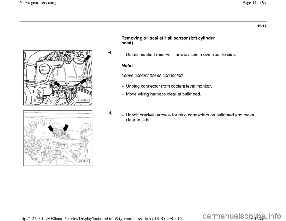
Leave coolant hoses connected. - Detach coolant reservoir -arrows- and move clear to side.
- Unplug connector from coolant level monitor.
- Move wiring harness clear at bulkhead.
- Unbolt bracket -arrows- for plug connectors on bulkhead and move
clear to side.
Pa
ge 14 of 99 Valve
gear, servicin
g
11/21/2002 htt
p://127.0.0.1:8080/audi/servlet/Dis
play?action=Goto&t
yp
e=re
pair&id=AUDI.B5.GE05.15.1
Page 18 of 99
15-18
Note:
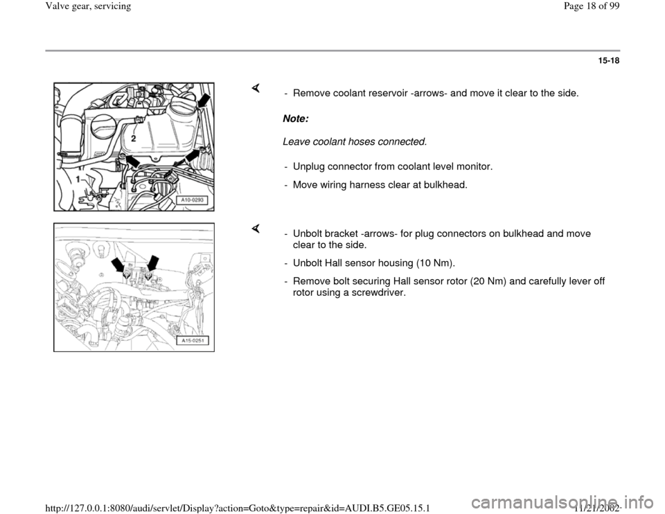
Leave coolant hoses connected. - Remove coolant reservoir -arrows- and move it clear to the side.
- Unplug connector from coolant level monitor.
- Move wiring harness clear at bulkhead.
- Unbolt bracket -arrows- for plug connectors on bulkhead and move
clear to the side.
- Unbolt Hall sensor housing (10 Nm).
- Remove bolt securing Hall sensor rotor (20 Nm) and carefully lever off
rotor using a screwdriver.
Pa
ge 18 of 99 Valve
gear, servicin
g
11/21/2002 htt
p://127.0.0.1:8080/audi/servlet/Dis
play?action=Goto&t
yp
e=re
pair&id=AUDI.B5.GE05.15.1
Page 26 of 99
15-26
WARNING!
Fuel system is under pressure. Before
opening the system, place a cloth around the
connection. Then release pressure by
carefully loosening the connection.
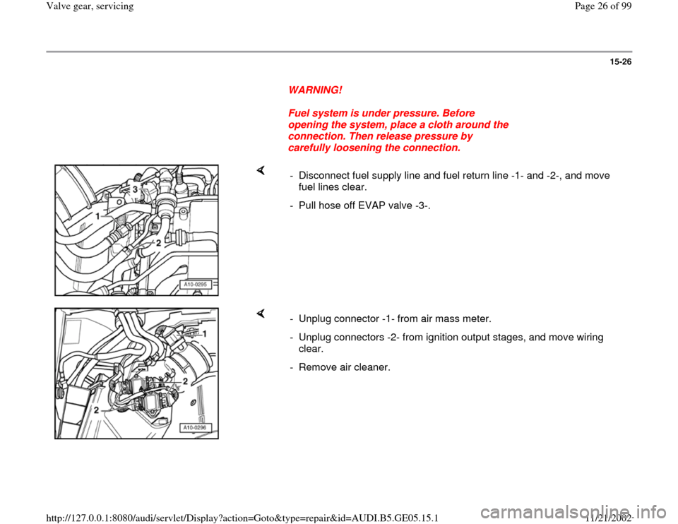
- Disconnect fuel supply line and fuel return line -1- and -2-, and move
fuel lines clear.
- Pull hose off EVAP valve -3-.
- Unplug connector -1- from air mass meter.
- Unplug connectors -2- from ignition output stages, and move wiring
clear.
- Remove air cleaner.
Pa
ge 26 of 99 Valve
gear, servicin
g
11/21/2002 htt
p://127.0.0.1:8080/audi/servlet/Dis
play?action=Goto&t
yp
e=re
pair&id=AUDI.B5.GE05.15.1
Page 30 of 99
15-30
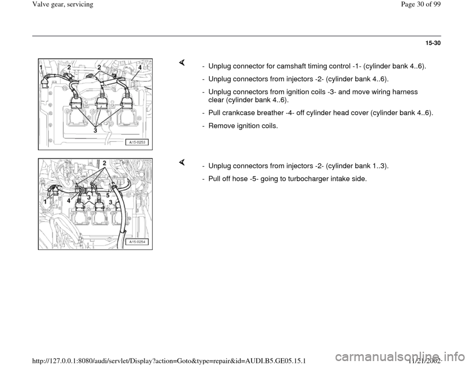
- Unplug connector for camshaft timing control -1- (cylinder bank 4..6).
- Unplug connectors from injectors -2- (cylinder bank 4..6).
- Unplug connectors from ignition coils -3- and move wiring harness
clear (cylinder bank 4..6).
- Pull crankcase breather -4- off cylinder head cover (cylinder bank 4..6).
- Remove ignition coils.
- Unplug connectors from injectors -2- (cylinder bank 1..3).
- Pull off hose -5- going to turbocharger intake side.
Pa
ge 30 of 99 Valve
gear, servicin
g
11/21/2002 htt
p://127.0.0.1:8080/audi/servlet/Dis
play?action=Goto&t
yp
e=re
pair&id=AUDI.B5.GE05.15.1
Page 44 of 99
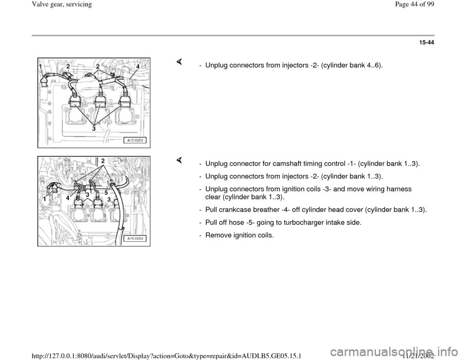
15-44
- Unplug connectors from injectors -2- (cylinder bank 4..6).
- Unplug connector for camshaft timing control -1- (cylinder bank 1..3).
- Unplug connectors from injectors -2- (cylinder bank 1..3).
- Unplug connectors from ignition coils -3- and move wiring harness
clear (cylinder bank 1..3).
- Pull crankcase breather -4- off cylinder head cover (cylinder bank 1..3).
- Pull off hose -5- going to turbocharger intake side.
- Remove ignition coils.
Pa
ge 44 of 99 Valve
gear, servicin
g
11/21/2002 htt
p://127.0.0.1:8080/audi/servlet/Dis
play?action=Goto&t
yp
e=re
pair&id=AUDI.B5.GE05.15.1
Page 61 of 99
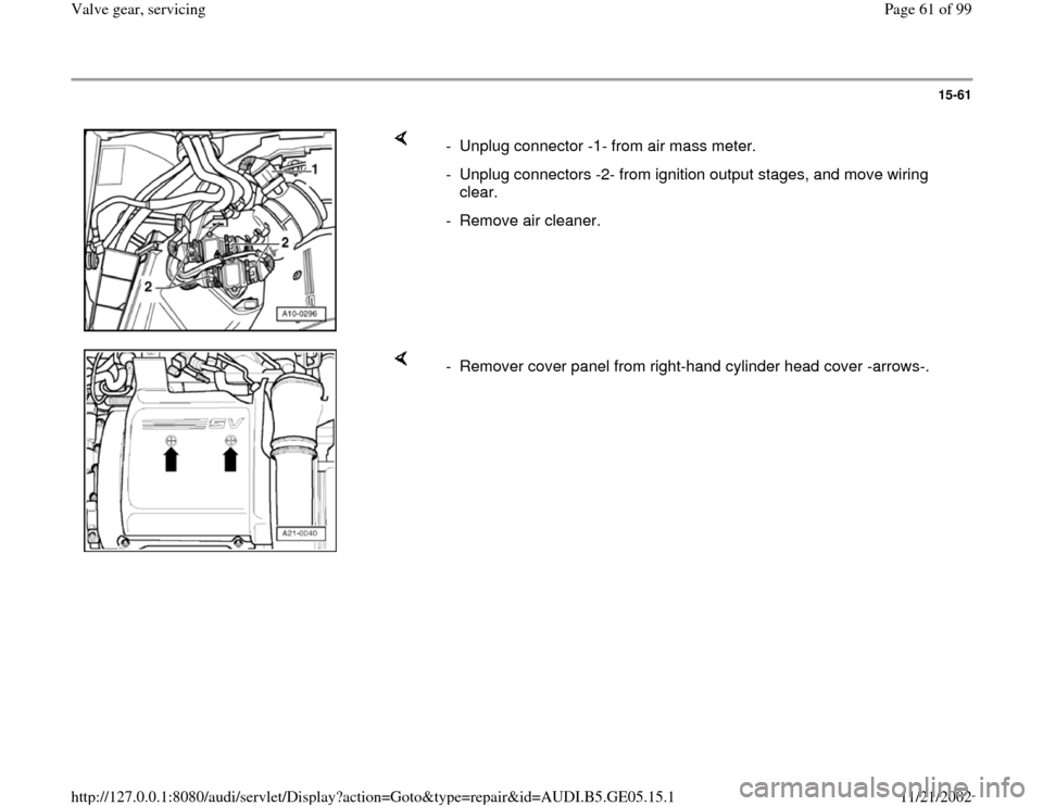
15-61
- Unplug connector -1- from air mass meter.
- Unplug connectors -2- from ignition output stages, and move wiring
clear.
- Remove air cleaner.
- Remover cover panel from right-hand cylinder head cover -arrows-.
Pa
ge 61 of 99 Valve
gear, servicin
g
11/21/2002 htt
p://127.0.0.1:8080/audi/servlet/Dis
play?action=Goto&t
yp
e=re
pair&id=AUDI.B5.GE05.15.1
Page 72 of 99
Electrical Wiring Diagrams, Troubleshooting & Component Locations
Pa
ge 72 of 99 Valve
gear, servicin
g
11/21/2002 htt
p://127.0.0.1:8080/audi/servlet/Dis
play?action=Goto&t
yp
e=re
pair&id=AUDI.B5.GE05.15.1
Page 73 of 99
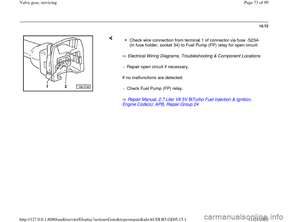
15-72
Electrical Wiring Diagrams, Troubleshooting & Component Locations
If no malfunctions are detected:
Repair Manual, 2.7 Liter V6 5V BiTurbo Fuel Injection & Ignition,
Engine Code(s): APB, Repair Group 24
Check wire connection from terminal 1 of connector via fuse -S234-
(in fuse holder, socket 34) to Fuel Pump (FP) relay for open circuit:
- Repair open circuit if necessary.
- Check Fuel Pump (FP) relay.
Pa
ge 73 of 99 Valve
gear, servicin
g
11/21/2002 htt
p://127.0.0.1:8080/audi/servlet/Dis
play?action=Goto&t
yp
e=re
pair&id=AUDI.B5.GE05.15.1
Page 74 of 99
15-73
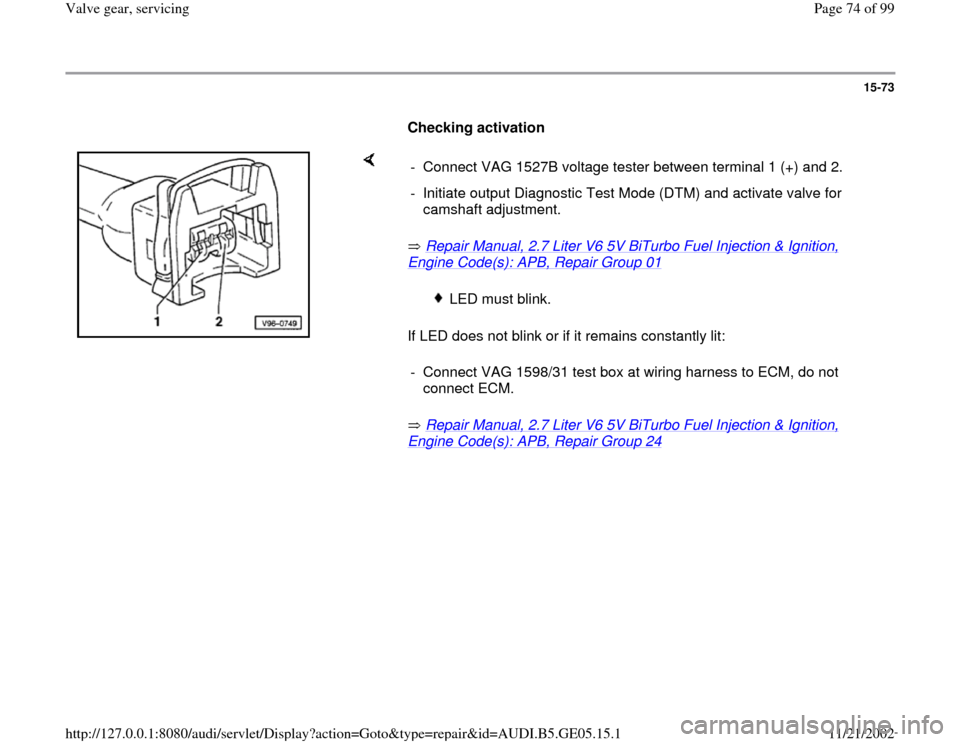
Checking activation
Repair Manual, 2.7 Liter V6 5V BiTurbo Fuel Injection & Ignition,
Engine Code(s): APB, Repair Group 01
If LED does not blink or if it remains constantly lit:
Repair Manual, 2.7 Liter V6 5V BiTurbo Fuel Injection & Ignition,
Engine Code(s): APB, Repair Group 24
- Connect VAG 1527B voltage tester between terminal 1 (+) and 2.
- Initiate output Diagnostic Test Mode (DTM) and activate valve for
camshaft adjustment.
LED must blink.
- Connect VAG 1598/31 test box at wiring harness to ECM, do not
connect ECM.
Pa
ge 74 of 99 Valve
gear, servicin
g
11/21/2002 htt
p://127.0.0.1:8080/audi/servlet/Dis
play?action=Goto&t
yp
e=re
pair&id=AUDI.B5.GE05.15.1
Page 75 of 99
15-74
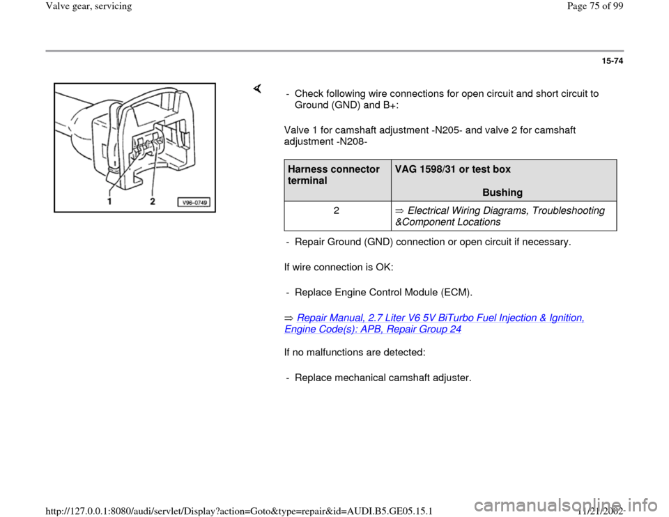
Valve 1 for camshaft adjustment -N205- and valve 2 for camshaft
adjustment -N208-
If wire connection is OK:
Repair Manual, 2.7 Liter V6 5V BiTurbo Fuel Injection & Ignition, Engine Code(s): APB, Repair Group 24
If no malfunctions are detected: - Check following wire connections for open circuit and short circuit to
Ground (GND) and B+:
Harness connector
terminal
VAG 1598/31 or test box
Bushing
2 Electrical Wiring Diagrams, Troubleshooting
&Component Locations
- Repair Ground (GND) connection or open circuit if necessary.
- Replace Engine Control Module (ECM).- Replace mechanical camshaft adjuster.
Pa
ge 75 of 99 Valve
gear, servicin
g
11/21/2002 htt
p://127.0.0.1:8080/audi/servlet/Dis
play?action=Goto&t
yp
e=re
pair&id=AUDI.B5.GE05.15.1