wiring AUDI A4 1998 B5 / 1.G ATW Engine Ignition System User Guide
[x] Cancel search | Manufacturer: AUDI, Model Year: 1998, Model line: A4, Model: AUDI A4 1998 B5 / 1.GPages: 59, PDF Size: 0.53 MB
Page 38 of 59
28-37
Test requirements:
Fuses for engine electronics OK
Electrical Wiring Diagrams, Troubleshooting &
Component Locations
Battery voltage at least 12.7 V
Generator OK
Test sequence
- Connect VAG1598/31 test box at wiring harness
to Engine Control Module (ECM), do not connect
ECM Page 24
-19
.
- Switch ignition on.
Note:
The plus voltage supply for the Engine Control
Module (ECM) travels via terminal 3 and 121
(terminal 15) as well as terminal 62 (terminal
30).
Pa
ge 38 of 59 I
gnition s
ystem, checkin
g
11/21/2002 htt
p://127.0.0.1:8080/audi/servlet/Dis
play?action=Goto&t
yp
e=re
pair&id=AUDI.B5.FU06.28.1
Page 41 of 59
- Check wire connections.
Electrical Wiring Diagrams, Troubleshooting &
Component Locations
Pa
ge 41 of 59 I
gnition s
ystem, checkin
g
11/21/2002 htt
p://127.0.0.1:8080/audi/servlet/Dis
play?action=Goto&t
yp
e=re
pair&id=AUDI.B5.FU06.28.1
Page 42 of 59
28-39
- Connect multimeter for voltage measurement as
follows:
VAG1598/31 test box
Socket
Measure to
121
1)
Engine Ground (GND)
1) The motronic Engine Control Module (ECM)
power supply relay -J271- continues to direct
current to terminal 121 of the Engine Control
Module (ECM) for up to 15 minutes after ignition
is switched off.
- Switch ignition on.
Specification: approx. battery voltage
If specified value is not obtained:
- Check wire connections.
Electrical Wiring Diagrams, Troubleshooting &
Component Locations
-
Check motronic Engine Control Module (ECM)
Pa
ge 42 of 59 I
gnition s
ystem, checkin
g
11/21/2002 htt
p://127.0.0.1:8080/audi/servlet/Dis
play?action=Goto&t
yp
e=re
pair&id=AUDI.B5.FU06.28.1
Page 46 of 59
28-42
Component location Overview of component
locations Page 24
-5
Note:
Knock Sensor (KS) 1 -G61- and Knock Sensor
(KS) 2 -G66- themselves cannot be electrically
tested.
Use only gold-plated terminals when servicing
harness connector for knock sensors.
For the knock sensors to function properly, it is
important that tightening torque be exactly 20
Nm.
Check harness connector from knock sensor to
wiring harness for corrosion.
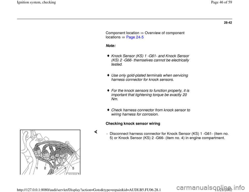
Checking knock sensor wiring
- Disconnect harness connector for Knock Sensor (KS) 1 -G61- (item no.
5) or Knock Sensor (KS) 2 -G66- (item no. 4) in engine compartment.
Pa
ge 46 of 59 I
gnition s
ystem, checkin
g
11/21/2002 htt
p://127.0.0.1:8080/audi/servlet/Dis
play?action=Goto&t
yp
e=re
pair&id=AUDI.B5.FU06.28.1
Page 47 of 59
28-43
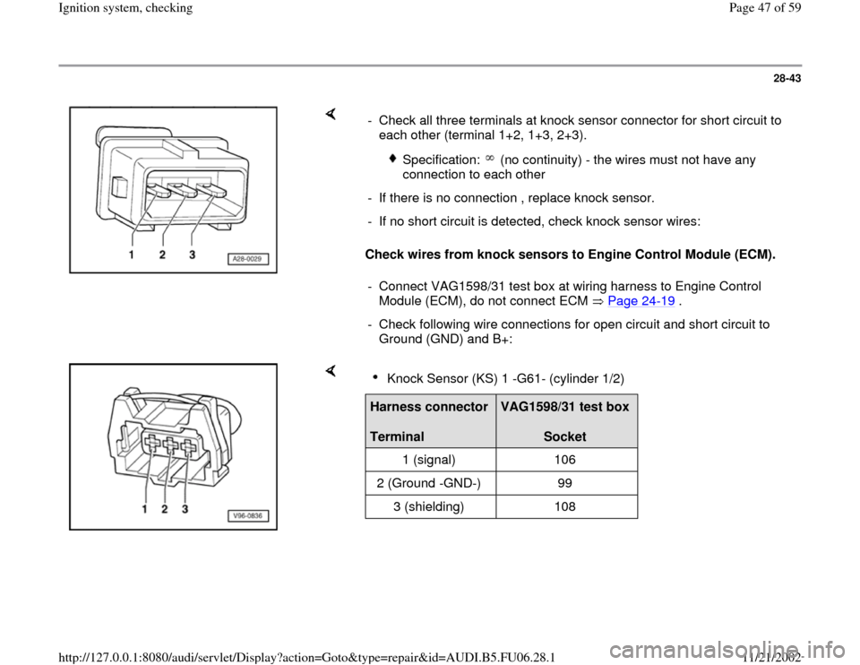
Check wires from knock sensors to Engine Control Module (ECM). - Check all three terminals at knock sensor connector for short circuit to
each other (terminal 1+2, 1+3, 2+3).
Specification: (no continuity) - the wires must not have any
connection to each other
- If there is no connection , replace knock sensor.
- If no short circuit is detected, check knock sensor wires:
- Connect VAG1598/31 test box at wiring harness to Engine Control
Module (ECM), do not connect ECM Page 24
-19
.
- Check following wire connections for open circuit and short circuit to
Ground (GND) and B+:
Knock Sensor (KS) 1 -G61- (cylinder 1/2)
Harness connector
Terminal
VAG1598/31 test box
Socket
1 (signal) 106
2 (Ground -GND-) 99
3 (shielding) 108
Pa
ge 47 of 59 I
gnition s
ystem, checkin
g
11/21/2002 htt
p://127.0.0.1:8080/audi/servlet/Dis
play?action=Goto&t
yp
e=re
pair&id=AUDI.B5.FU06.28.1
Page 53 of 59
28-49
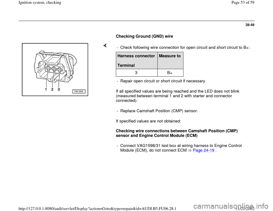
Checking Ground (GND) wire
If all specified values are being reached and the LED does not blink
(measured between terminal 1 and 2 with starter and connector
connected):
If specified values are not obtained:
Checking wire connections between Camshaft Position (CMP)
sensor and Engine Control Module (ECM) - Check following wire connection for open circuit and short circuit to B+:Harness connector
Terminal
Measure to
3 B+
- Repair open circuit or short circuit if necessary.
- Replace Camshaft Position (CMP) sensor.
- Connect VAG1598/31 test box at wiring harness to Engine Control
Module (ECM), do not connect ECM Page 24
-19
.
Pa
ge 53 of 59 I
gnition s
ystem, checkin
g
11/21/2002 htt
p://127.0.0.1:8080/audi/servlet/Dis
play?action=Goto&t
yp
e=re
pair&id=AUDI.B5.FU06.28.1