wiring AUDI A4 1998 B5 / 1.G ATW Engine Ignition System Workshop Manual
[x] Cancel search | Manufacturer: AUDI, Model Year: 1998, Model line: A4, Model: AUDI A4 1998 B5 / 1.GPages: 59, PDF Size: 0.53 MB
Page 2 of 59
28-2
Safety precautions
To reduce the risk of personal injury and/or
damage to the fuel injection and ignition system,
always observe the following:
Do not touch or disconnect ignition wires when
engine is running or turning at starting RPM.
Always switch ignition off before disconnecting
or reconnecting wires for the injection and
ignition system, including high voltage wiring
and test leads.
If engine is to be cranked at starting RPM
without starting (e.g. for compression testing),
disconnect connector from ignition coils and
from fuel injectors.
It is possible that the control module will
recognize a malfunction and store a DTC during
some tests. After completing all tests and
repairs, DTC memory should therefore be
checked and erased if necessary. Readiness
code must be generated after DTC memory is
erased Page 01
-73
.
Always switch ignition off before cleaning
engine.
Pa
ge 2 of 59 I
gnition s
ystem, checkin
g
11/21/2002 htt
p://127.0.0.1:8080/audi/servlet/Dis
play?action=Goto&t
yp
e=re
pair&id=AUDI.B5.FU06.28.1
Page 8 of 59
28-7
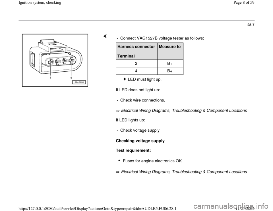
If LED does not light up:
Electrical Wiring Diagrams, Troubleshooting & Component Locations
If LED lights up:
Checking voltage supply
Test requirement:
Electrical Wiring Diagrams, Troubleshooting & Component Locations - Connect VAG1527B voltage tester as follows:Harness connector
Terminal
Measure to
2 B+
4 B+
LED must light up.
- Check wire connections.
- Check voltage supply
Fuses for engine electronics OK
Pa
ge 8 of 59 I
gnition s
ystem, checkin
g
11/21/2002 htt
p://127.0.0.1:8080/audi/servlet/Dis
play?action=Goto&t
yp
e=re
pair&id=AUDI.B5.FU06.28.1
Page 12 of 59
28-11
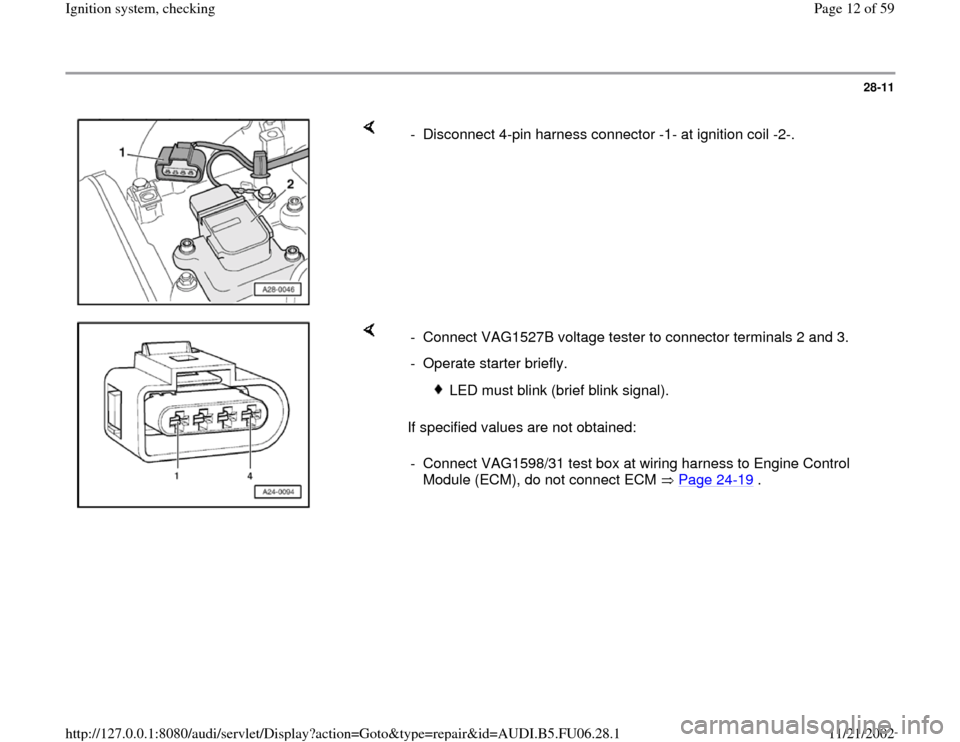
- Disconnect 4-pin harness connector -1- at ignition coil -2-.
If specified values are not obtained: - Connect VAG1527B voltage tester to connector terminals 2 and 3.
- Operate starter briefly.
LED must blink (brief blink signal).
- Connect VAG1598/31 test box at wiring harness to Engine Control
Module (ECM), do not connect ECM Page 24
-19
.
Pa
ge 12 of 59 I
gnition s
ystem, checkin
g
11/21/2002 htt
p://127.0.0.1:8080/audi/servlet/Dis
play?action=Goto&t
yp
e=re
pair&id=AUDI.B5.FU06.28.1
Page 15 of 59
28-14
Note:
The motronic Engine Control Module (ECM)
power supply relay -J271- supplies voltage to the
ignition coils with power output stages and the
Engine Control Module (ECM) at pin 121.
Test requirement:
Fuses for engine electronics OK
Electrical Wiring Diagrams, Troubleshooting &
Component Locations
Test sequence
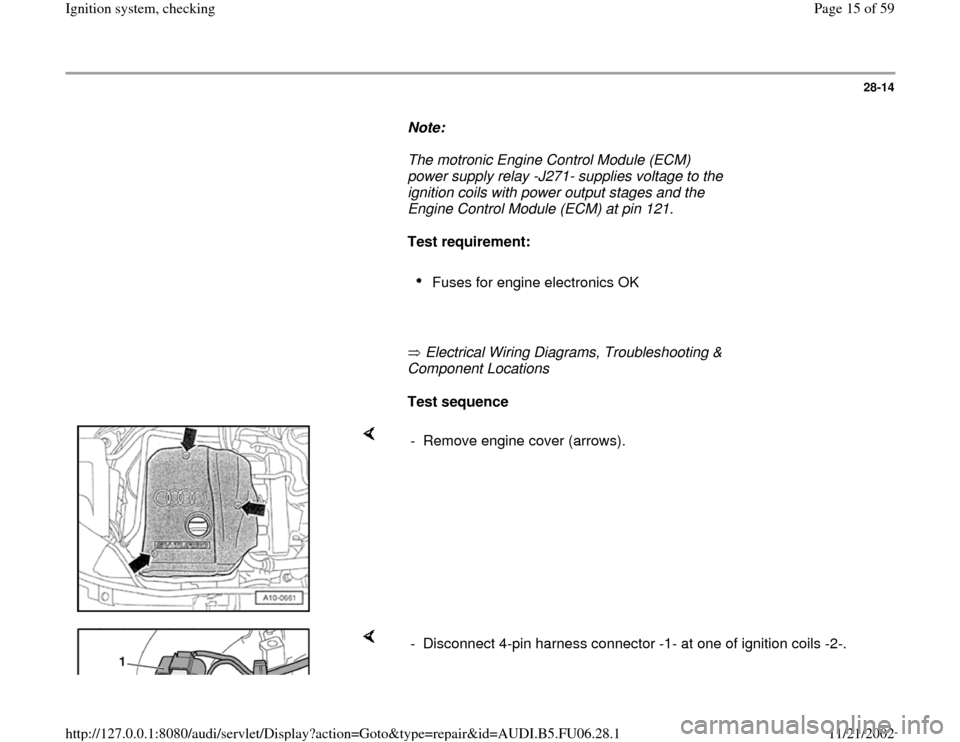
- Remove engine cover (arrows).
- Disconnect 4-pin harness connector -1- at one of ignition coils -2-.
Pa
ge 15 of 59 I
gnition s
ystem, checkin
g
11/21/2002 htt
p://127.0.0.1:8080/audi/servlet/Dis
play?action=Goto&t
yp
e=re
pair&id=AUDI.B5.FU06.28.1
Page 18 of 59
28-17
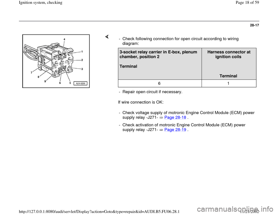
If wire connection is OK: - Check following connection for open circuit according to wiring
diagram: 3-socket relay carrier in E-box, plenum
chamber, position 2
Terminal
Harness connector at
ignition coils
Terminal
6 1
- Repair open circuit if necessary.
- Check voltage supply of motronic Engine Control Module (ECM) power
supply relay -J271- Page 28
-18
.
- Check activation of motronic Engine Control Module (ECM) power
supply relay -J271- Page 28
-19
.
Pa
ge 18 of 59 I
gnition s
ystem, checkin
g
11/21/2002 htt
p://127.0.0.1:8080/audi/servlet/Dis
play?action=Goto&t
yp
e=re
pair&id=AUDI.B5.FU06.28.1
Page 19 of 59
28-18
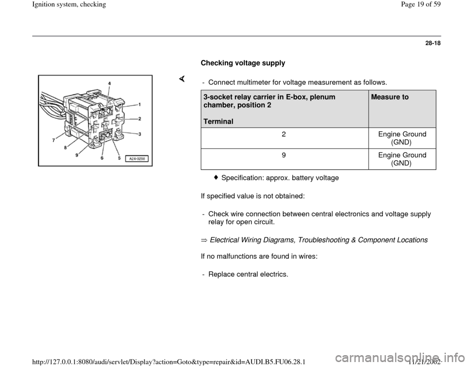
Checking voltage supply
If specified value is not obtained:
Electrical Wiring Diagrams, Troubleshooting & Component Locations
If no malfunctions are found in wires: - Connect multimeter for voltage measurement as follows.3-socket relay carrier in E-box, plenum
chamber, position 2
Terminal
Measure to
2 Engine Ground
(GND)
9 Engine Ground
(GND)
Specification: approx. battery voltage
- Check wire connection between central electronics and voltage supply
relay for open circuit.
- Replace central electrics.
Pa
ge 19 of 59 I
gnition s
ystem, checkin
g
11/21/2002 htt
p://127.0.0.1:8080/audi/servlet/Dis
play?action=Goto&t
yp
e=re
pair&id=AUDI.B5.FU06.28.1
Page 20 of 59
28-19
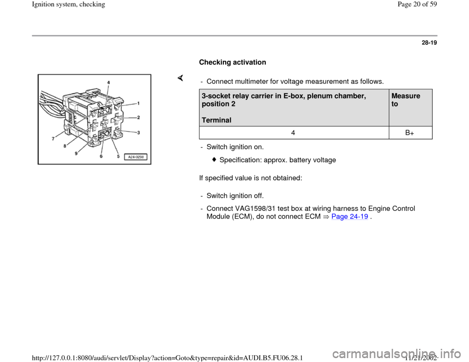
Checking activation
If specified value is not obtained: - Connect multimeter for voltage measurement as follows.3-socket relay carrier in E-box, plenum chamber,
position 2
Terminal
Measure
to
4 B+
- Switch ignition on.
Specification: approx. battery voltage
- Switch ignition off.
- Connect VAG1598/31 test box at wiring harness to Engine Control
Module (ECM), do not connect ECM Page 24
-19
.
Pa
ge 20 of 59 I
gnition s
ystem, checkin
g
11/21/2002 htt
p://127.0.0.1:8080/audi/servlet/Dis
play?action=Goto&t
yp
e=re
pair&id=AUDI.B5.FU06.28.1
Page 25 of 59
28-24
Checking wire connections
- Connect VAG1598/31 test box at wiring harness
to Engine Control Module (ECM), do not connect
ECM Page 24
-19
.
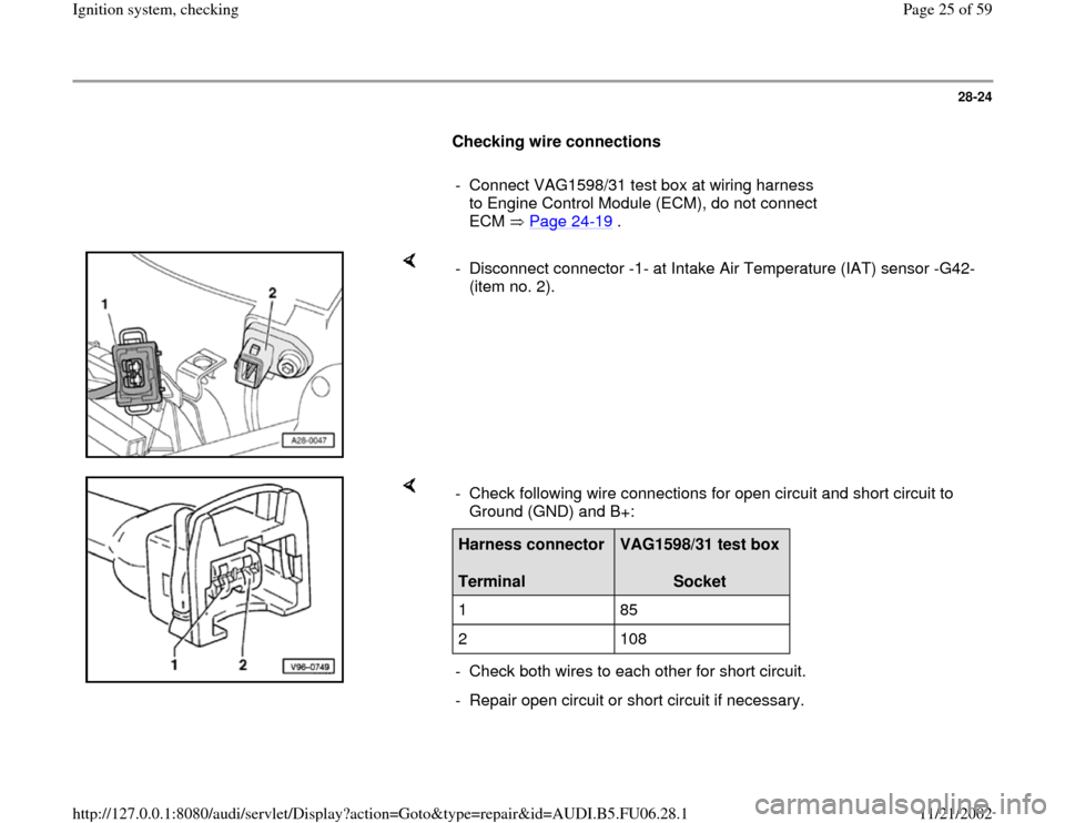
- Disconnect connector -1- at Intake Air Temperature (IAT) sensor -G42-
(item no. 2).
- Check following wire connections for open circuit and short circuit to
Ground (GND) and B+: Harness connector
Terminal
VAG1598/31 test box
Socket
1 85
2 108
- Check both wires to each other for short circuit.
- Repair open circuit or short circuit if necessary.
Pa
ge 25 of 59 I
gnition s
ystem, checkin
g
11/21/2002 htt
p://127.0.0.1:8080/audi/servlet/Dis
play?action=Goto&t
yp
e=re
pair&id=AUDI.B5.FU06.28.1
Page 30 of 59
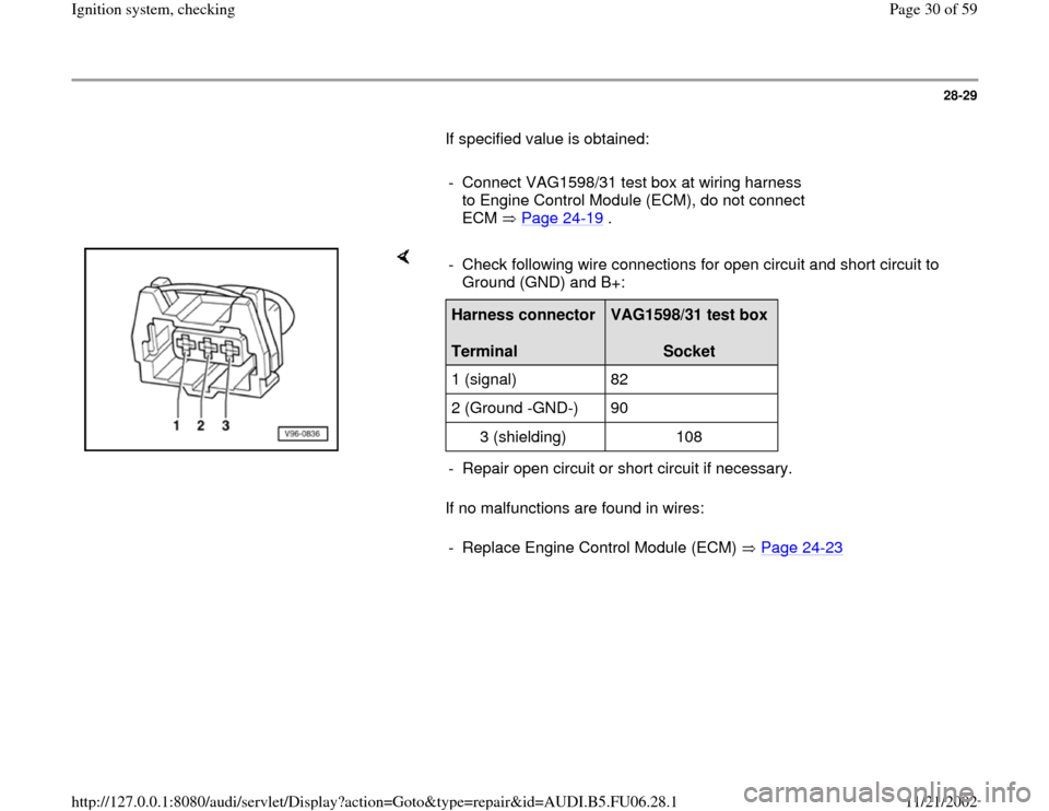
28-29
If specified value is obtained:
- Connect VAG1598/31 test box at wiring harness
to Engine Control Module (ECM), do not connect
ECM Page 24
-19
.
If no malfunctions are found in wires: - Check following wire connections for open circuit and short circuit to
Ground (GND) and B+: Harness connector
Terminal
VAG1598/31 test box
Socket
1 (signal) 82
2 (Ground -GND-) 90
3 (shielding) 108
- Repair open circuit or short circuit if necessary.
- Replace Engine Control Module (ECM) Page 24
-23
Pa
ge 30 of 59 I
gnition s
ystem, checkin
g
11/21/2002 htt
p://127.0.0.1:8080/audi/servlet/Dis
play?action=Goto&t
yp
e=re
pair&id=AUDI.B5.FU06.28.1
Page 35 of 59
28-34
If specified value is obtained:
- Connect VAG1598/31 test box at wiring harness
to Engine Control Module (ECM), do not connect
ECM Page 24
-19
.
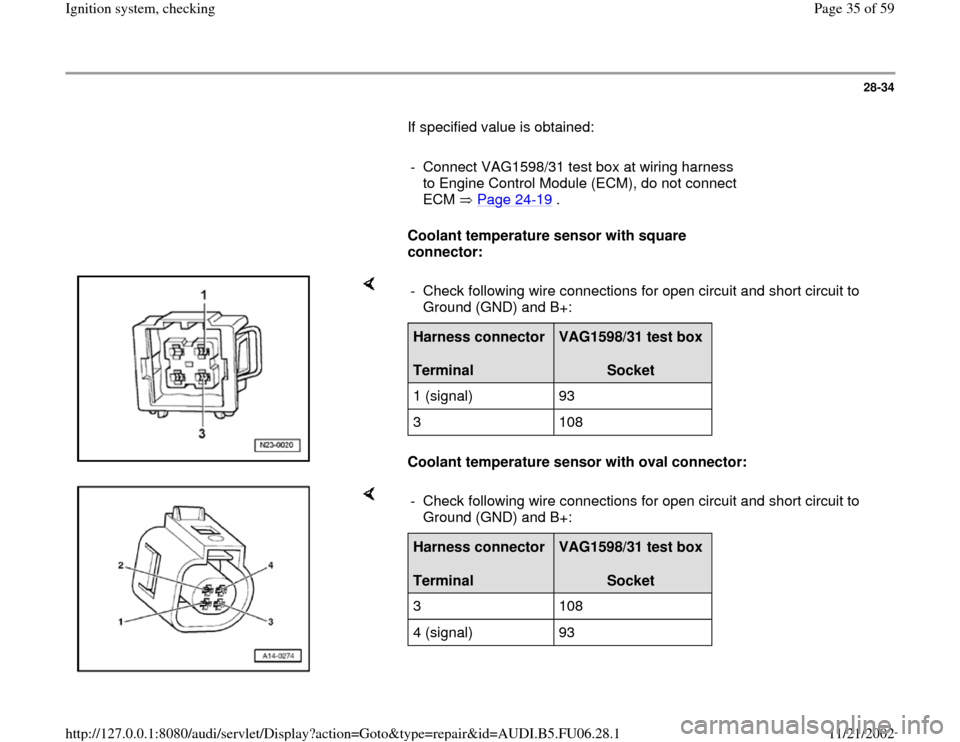
Coolant temperature sensor with square
connector:
Coolant temperature sensor with oval connector: - Check following wire connections for open circuit and short circuit to
Ground (GND) and B+: Harness connector
Terminal
VAG1598/31 test box
Socket
1 (signal) 93
3 108
- Check following wire connections for open circuit and short circuit to
Ground (GND) and B+: Harness connector
Terminal
VAG1598/31 test box
Socket
3 108
4 (signal) 93
Pa
ge 35 of 59 I
gnition s
ystem, checkin
g
11/21/2002 htt
p://127.0.0.1:8080/audi/servlet/Dis
play?action=Goto&t
yp
e=re
pair&id=AUDI.B5.FU06.28.1