engine AUDI A4 1998 B5 / 1.G ATW Engine Motronic Fuel Injection Syst
[x] Cancel search | Manufacturer: AUDI, Model Year: 1998, Model line: A4, Model: AUDI A4 1998 B5 / 1.GPages: 81, PDF Size: 1.03 MB
Page 50 of 81
24-45
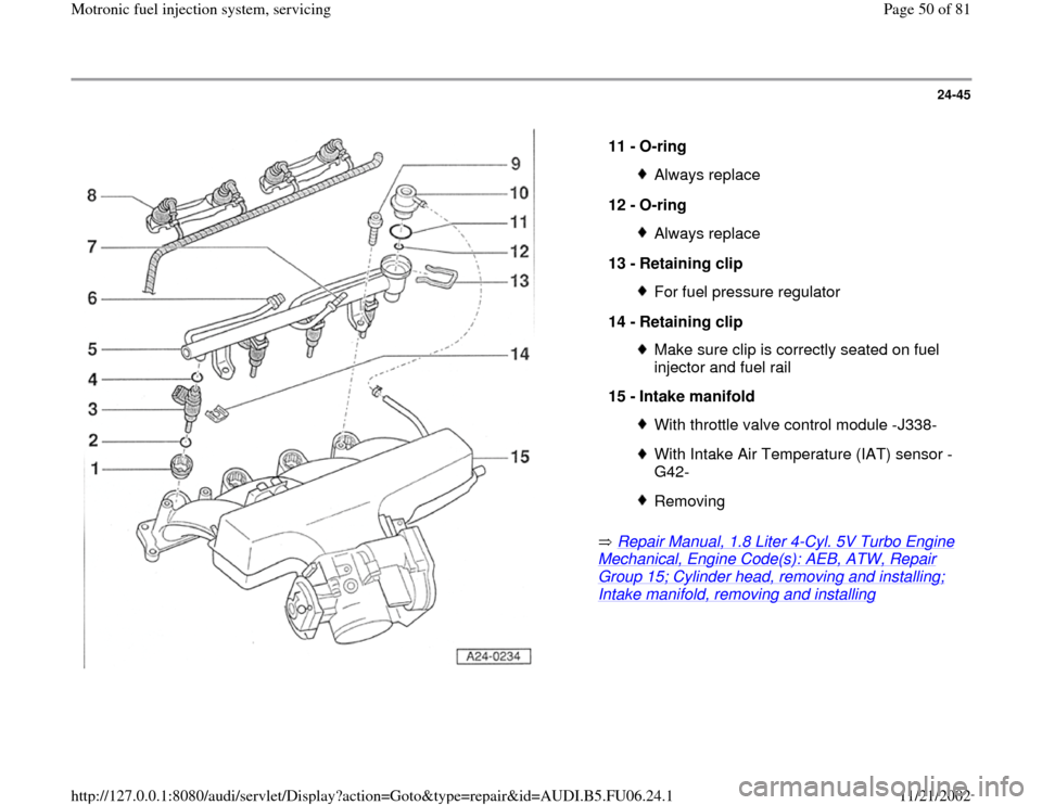
Repair Manual, 1.8 Liter 4
-Cyl. 5V Turbo Engine
Mechanical, Engine Code(s): AEB, ATW, Repair Group 15; Cylinder head, removing and installing; Intake manifold, removing and installing
11 -
O-ring
Always replace
12 -
O-ring Always replace
13 -
Retaining clip For fuel pressure regulator
14 -
Retaining clip Make sure clip is correctly seated on fuel
injector and fuel rail
15 -
Intake manifold With throttle valve control module -J338-With Intake Air Temperature (IAT) sensor -
G42- Removing
Pa
ge 50 of 81 Motronic fuel in
jection s
ystem, servicin
g
11/21/2002 htt
p://127.0.0.1:8080/audi/servlet/Dis
play?action=Goto&t
yp
e=re
pair&id=AUDI.B5.FU06.24.1
Page 51 of 81
24-46
Fuel injectors, removing and installing
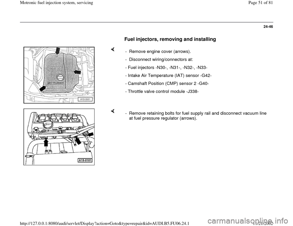
- Remove engine cover (arrows).
- Disconnect wiring/connectors at:
- Fuel injectors -N30-, -N31-, -N32-, -N33-
- Intake Air Temperature (IAT) sensor -G42-
- Camshaft Position (CMP) sensor 2 -G40-
- Throttle valve control module -J338-
- Remove retaining bolts for fuel supply rail and disconnect vacuum line
at fuel pressure regulator (arrows).
Pa
ge 51 of 81 Motronic fuel in
jection s
ystem, servicin
g
11/21/2002 htt
p://127.0.0.1:8080/audi/servlet/Dis
play?action=Goto&t
yp
e=re
pair&id=AUDI.B5.FU06.24.1
Page 52 of 81
24-47
- Disconnect fuel distributor with injectors from
intake plenum and set aside in rear of engine
compartment on a clean cloth.
WARNING!
Fuel system is under pressure! Before
opening system, place rags around the
connection point. Then release pressure by
carefully loosening connection.
- Disengage retaining clip and remove fuel
injector.
Note:
Fuel lines must be removed before replacing fuel
distributor.
Installation is reverse of removal, noting the
following:
Remove O-rings at all opened connections.
(Never remove plastic cap from valve head
to replace front O-ring - pry O-ring off over
plastic cap).
Lightly lubricate O-rings with clean engine
oil.
Pa
ge 52 of 81 Motronic fuel in
jection s
ystem, servicin
g
11/21/2002 htt
p://127.0.0.1:8080/audi/servlet/Dis
play?action=Goto&t
yp
e=re
pair&id=AUDI.B5.FU06.24.1
Page 55 of 81
24-50
Test requirement:
Fuel pressure OK, checking Page 24
-33
.
Test sequence
- Remove fuel distributor including fuel injectors
from intake manifold Page 24
-46
. Fuel lines
remain connected.
- Connect VAG1598/31 test box at wiring harness
to Engine Control Module (ECM), do not connect
ECM Page 24
-19
.
Checking Proper Seal
- Bridge terminals 1 and 65 at test box using wires
from VAG1594A adapter test kit.
- Switch ignition on.
Fuel Pump (FP) must run.
- Check proper seal of fuel injectors (visual
inspection). With Fuel Pump (FP) running, only 1
to 2 drops per minute may drip out per injector.
-
If fuel loss is greater, stop Fuel Pump (FP) from
Pa
ge 55 of 81 Motronic fuel in
jection s
ystem, servicin
g
11/21/2002 htt
p://127.0.0.1:8080/audi/servlet/Dis
play?action=Goto&t
yp
e=re
pair&id=AUDI.B5.FU06.24.1
Page 57 of 81
24-51
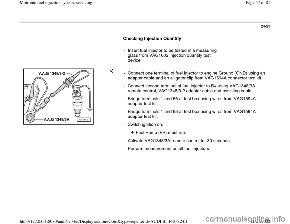
Checking Injection Quantity
- Insert fuel injector to be tested in a measuring
glass from VAG1602 injection quantity test
device.
- Connect one terminal of fuel injector to engine Ground (GND) using an
adapter cable and an alligator clip from VAG1594A connector test kit.
- Connect second terminal of fuel injector to B+ using VAG1348/3A
remote control, VAG1348/3-2 adapter cable and assisting cable.
- Bridge terminals 1 and 65 at test box using wires from VAG1594A
adapter test kit.
- Bridge terminals 1 and 65 at test box using wires from VAG1594A
adapter test kit.
- Switch ignition on.
Fuel Pump (FP) must run.
- Activate VAG1348/3A remote control for 30 seconds.
- Perform measurement on all fuel injectors.
Pa
ge 57 of 81 Motronic fuel in
jection s
ystem, servicin
g
11/21/2002 htt
p://127.0.0.1:8080/audi/servlet/Dis
play?action=Goto&t
yp
e=re
pair&id=AUDI.B5.FU06.24.1
Page 60 of 81
24-54
Component location Overview of component
locations Page 24
-5 .
Voltage is supplied to the Fuel Pump (FP) and
several components of the injection system via
the Fuel Pump (FP) relay -J17-.
Engine must be turning for Fuel Pump (FP) relay
-J17- to close. This means that the relay does
not receive Ground (GND) (via ECM) until the
ECM recognizes RPM signals.
Test requirement:
Battery voltage at least 12.7 V
Function test of Fuel Pump (FP) relay
- Remove driver-side storage compartment.
Repair Manual, Body Interior, Repair Group
68
- Connect VAS5051 tester or VAG1551 scan tool
and select control module for engine electronics
using "address word" 01 Page 01
-10
. Ignition
must remain switched on.
-
Initiate output Diagnostic Test Mode (DTM)
Pa
ge 60 of 81 Motronic fuel in
jection s
ystem, servicin
g
11/21/2002 htt
p://127.0.0.1:8080/audi/servlet/Dis
play?action=Goto&t
yp
e=re
pair&id=AUDI.B5.FU06.24.1
Page 63 of 81
24-56
If specified value is not obtained:
- Replace central electrics.
Checking activation of Fuel Pump (FP) relay
- Switch ignition off.
- Connect VAG1598/31 test box at wiring harness
to Engine Control Module (ECM), do not connect
ECM Page 24
-19
.
- Switch ignition on.
- Bridge terminals 1 and 65 at test box using wires
from VAG1594A adapter test kit.
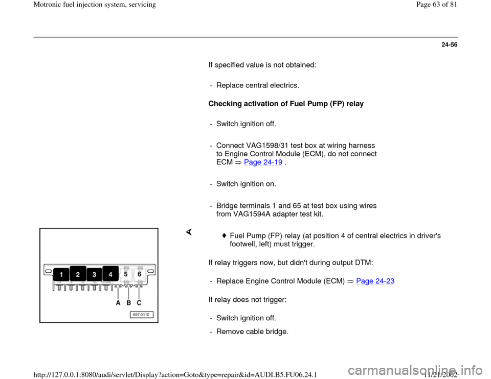
If relay triggers now, but didn't during output DTM:
If relay does not trigger:
Fuel Pump (FP) relay (at position 4 of central electrics in driver's
footwell, left) must trigger.
- Replace Engine Control Module (ECM) Page 24
-23
- Switch ignition off.
- Remove cable bridge.
Pa
ge 63 of 81 Motronic fuel in
jection s
ystem, servicin
g
11/21/2002 htt
p://127.0.0.1:8080/audi/servlet/Dis
play?action=Goto&t
yp
e=re
pair&id=AUDI.B5.FU06.24.1
Page 65 of 81
24-57
If specified value is not obtained:
Electrical Wiring Diagrams, Troubleshooting & Component Locations
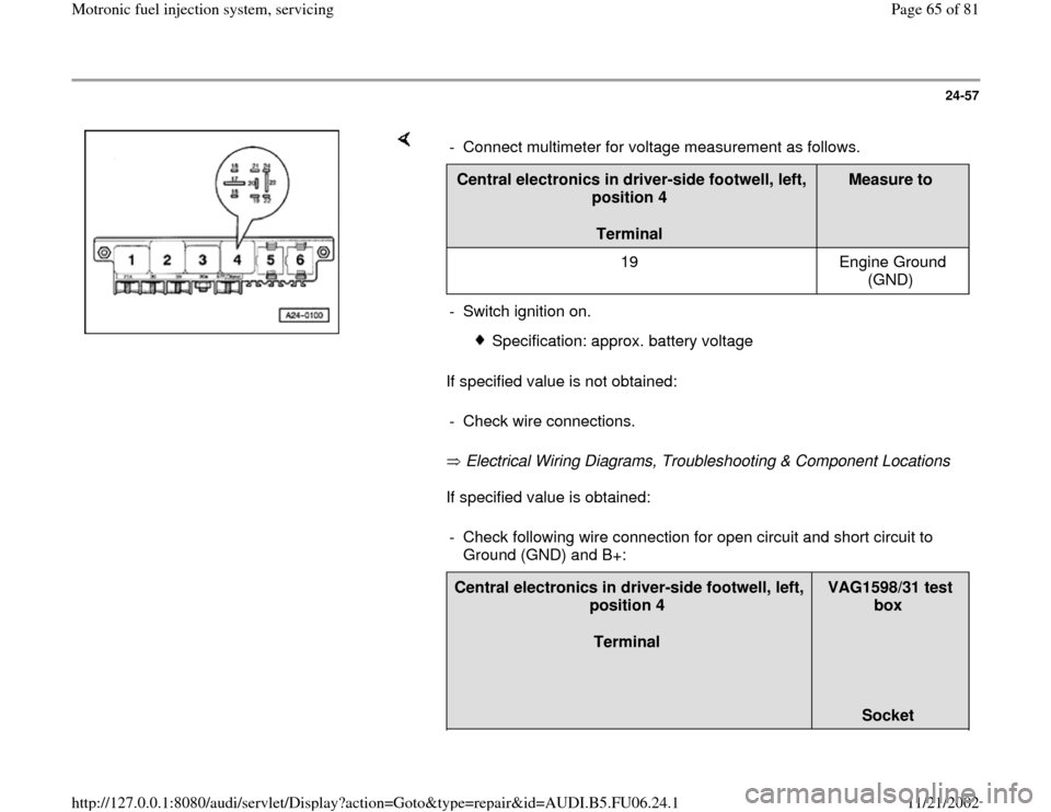
If specified value is obtained: - Connect multimeter for voltage measurement as follows.Central electronics in driver-side footwell, left,
position 4
Terminal
Measure to
19 Engine Ground
(GND)
- Switch ignition on.
Specification: approx. battery voltage
- Check wire connections.
- Check following wire connection for open circuit and short circuit to
Ground (GND) and B+: Central electronics in driver-side footwell, left,
position 4
Terminal
VAG1598/31 test
box
Socket
Pa
ge 65 of 81 Motronic fuel in
jection s
ystem, servicin
g
11/21/2002 htt
p://127.0.0.1:8080/audi/servlet/Dis
play?action=Goto&t
yp
e=re
pair&id=AUDI.B5.FU06.24.1
Page 67 of 81
24-58
- Repair open circuit or short circuit if
necessary.
If no malfunctions are detected:
- Replace Fuel Pump (FP) relay -J17-.
- Re-connect Engine Control Module (ECM).
Check voltage supply for Fuel Pump (FP) and
components
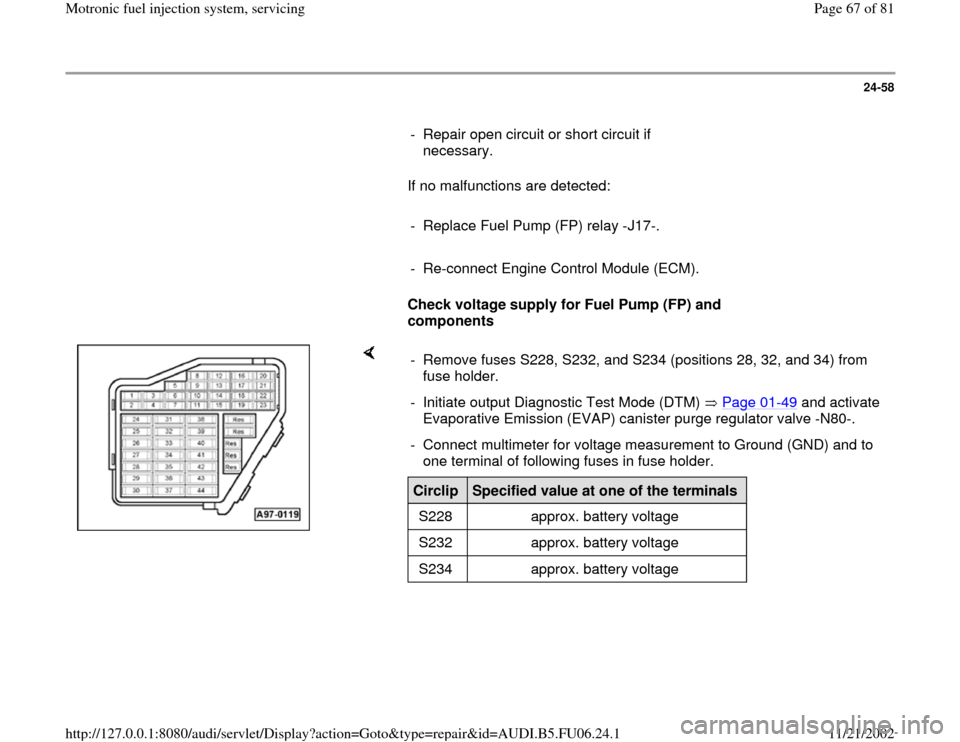
- Remove fuses S228, S232, and S234 (positions 28, 32, and 34) from
fuse holder.
- Initiate output Diagnostic Test Mode (DTM) Page 01
-49
and activate
Evaporative Emission (EVAP) canister purge regulator valve -N80-.
- Connect multimeter for voltage measurement to Ground (GND) and to
one terminal of following fuses in fuse holder. Circlip
Specified value at one of the terminals
S228 approx. battery voltage
S232 approx. battery voltage
S234 approx. battery voltage
Pa
ge 67 of 81 Motronic fuel in
jection s
ystem, servicin
g
11/21/2002 htt
p://127.0.0.1:8080/audi/servlet/Dis
play?action=Goto&t
yp
e=re
pair&id=AUDI.B5.FU06.24.1
Page 70 of 81
24-61
Component location Overview of component
locations Page 24
-5
Test requirements:
Coolant Temperature at least 80 C.
Electrical consumers switched off (radiator
fan must NOT run during test).
A/C switched off.
Checking function
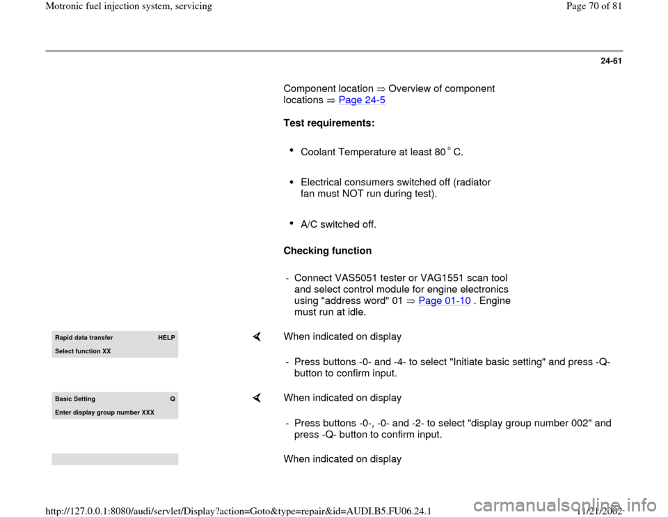
- Connect VAS5051 tester or VAG1551 scan tool
and select control module for engine electronics
using "address word" 01 Page 01
-10
. Engine
must run at idle.
Rapid data transfer
HELP
Select function XX
When indicated on display
- Press buttons -0- and -4- to select "Initiate basic setting" and press -Q-
button to confirm input.
Basic Setting
Q
Enter displa
y group number XXX
When indicated on display
- Press buttons -0-, -0- and -2- to select "display group number 002" and
press -Q- button to confirm input. When indicated on display
Pa
ge 70 of 81 Motronic fuel in
jection s
ystem, servicin
g
11/21/2002 htt
p://127.0.0.1:8080/audi/servlet/Dis
play?action=Goto&t
yp
e=re
pair&id=AUDI.B5.FU06.24.1