AUDI A4 1998 B5 / 1.G AWM Engine Cylinder Head Remove And Install Workshop Manual
Manufacturer: AUDI, Model Year: 1998,
Model line: A4,
Model: AUDI A4 1998 B5 / 1.G
Pages: 42, PDF Size: 0.87 MB
AUDI A4 1998 B5 / 1.G AWM Engine Cylinder Head Remove And Install Workshop Manual
A4 1998 B5 / 1.G
AUDI
AUDI
https://www.carmanualsonline.info/img/6/933/w960_933-0.png
AUDI A4 1998 B5 / 1.G AWM Engine Cylinder Head Remove And Install Workshop Manual
Trending: check oil, engine coolant, oil dipstick, spark plugs replace, clock, wiring, engine oil
Page 1 of 42
15-1
Cylinder head, removing and
installing
Note:
Always replace the cylinder head bolts.
When performing repairs, replace seals,
gaskets, self-locking nuts and bolts which have
a specified tightening angle.
The hose connectors and hoses of charge air
system must be free of oil and grease before
assembling.
When installing an exchange cylinder head with
the camshafts installed, the contact surfaces
between bucket tappet and cam running
surface must be oiled after installation of the
cylinder head.
The plastic protectors fitted to protect the open
valves must only be removed immediately
before installing the cylinder head.
When installing a new cylinder head or cylinder
head gasket, drain off all the old coolant and re-
fill with new coolant.
Pa
ge 1 of 42 C
ylinder head, removin
g and installin
g
11/21/2002 htt
p://127.0.0.1:8080/audi/servlet/Dis
play?action=Goto&t
yp
e=re
pair&id=AUDI.B5.GE06.15.1
Page 2 of 42
Cylinder heads which have cracks between the
valve seats or between valve seat inserts and
the spark plug thread can be used further
without reducing service life, provided the
cracks do not exceed a maximum of 0.3 mm in
width, or when no more than the first 4 turns of
the spark plug threads are cracked.
Pa
ge 2 of 42 C
ylinder head, removin
g and installin
g
11/21/2002 htt
p://127.0.0.1:8080/audi/servlet/Dis
play?action=Goto&t
yp
e=re
pair&id=AUDI.B5.GE06.15.1
Page 3 of 42
15-2
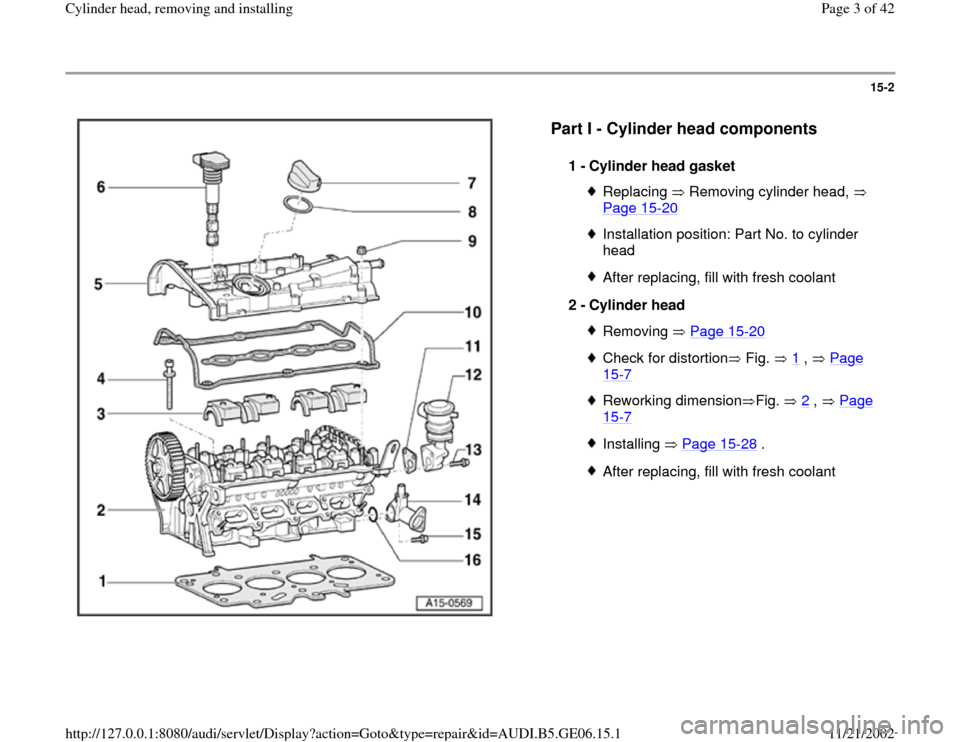
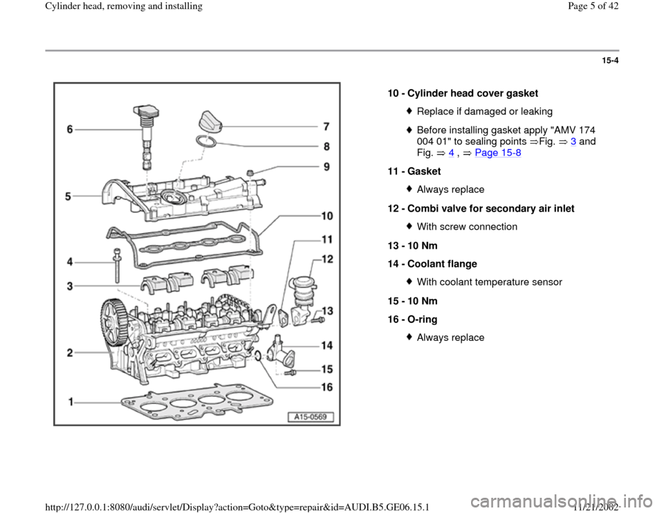
Part I - Cylinder head components
1 -
Cylinder head gasket
Replacing Removing cylinder head,
Page 15
-20
Installation position: Part No. to cylinder
head After replacing, fill with fresh coolant
2 -
Cylinder head Removing Page 15
-20
Check for distortion Fig. 1
, Page
15
-7
Reworking dimension Fig. 2
, Page
15
-7
Installing Page 15
-28
.
After replacing, fill with fresh coolant
Pa
ge 3 of 42 C
ylinder head, removin
g and installin
g
11/21/2002 htt
p://127.0.0.1:8080/audi/servlet/Dis
play?action=Goto&t
yp
e=re
pair&id=AUDI.B5.GE06.15.1
Page 4 of 42
15-3
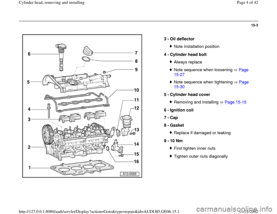
3 -
Oil deflector
Note installation position
4 -
Cylinder head bolt Always replaceNote sequence when loosening Page 15
-27
Note sequence when tightening Page 15
-30
5 -
Cylinder head cover
Removing and installing Page 15
-15
6 -
Ignition coil
7 -
Cap
8 -
Gasket
Replace if damaged or leaking
9 -
10 Nm First tighten inner nutsTighten outer nuts diagonally
Pa
ge 4 of 42 C
ylinder head, removin
g and installin
g
11/21/2002 htt
p://127.0.0.1:8080/audi/servlet/Dis
play?action=Goto&t
yp
e=re
pair&id=AUDI.B5.GE06.15.1
Page 5 of 42
15-4
10 -
Cylinder head cover gasket
Replace if damaged or leakingBefore installing gasket apply "AMV 174
004 01" to sealing points Fig. 3
and
Fig. 4
, Page 15
-8
11 -
Gasket
Always replace
12 -
Combi valve for secondary air inlet With screw connection
13 -
10 Nm
14 -
Coolant flange With coolant temperature sensor
15 -
10 Nm
16 -
O-ring Always replace
Pa
ge 5 of 42 C
ylinder head, removin
g and installin
g
11/21/2002 htt
p://127.0.0.1:8080/audi/servlet/Dis
play?action=Goto&t
yp
e=re
pair&id=AUDI.B5.GE06.15.1
Page 6 of 42
15-5
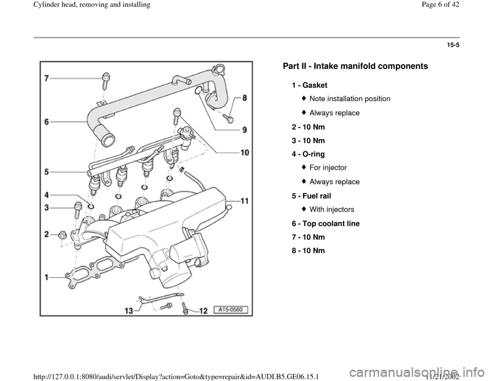
Part II - Intake manifold components
1 -
Gasket
Note installation positionAlways replace
2 -
10 Nm
3 -
10 Nm
4 -
O-ring For injectorAlways replace
5 -
Fuel rail With injectors
6 -
Top coolant line
7 -
10 Nm
8 -
10 Nm
Pa
ge 6 of 42 C
ylinder head, removin
g and installin
g
11/21/2002 htt
p://127.0.0.1:8080/audi/servlet/Dis
play?action=Goto&t
yp
e=re
pair&id=AUDI.B5.GE06.15.1
Page 7 of 42
15-6
9 -
O-ring
For top coolant lineAlways replace
10 -
10 Nm
11 -
Intake manifold Removing and installing Page 15
-9
12 -
20 Nm
13 -
Support
For intake manifold
Pa
ge 7 of 42 C
ylinder head, removin
g and installin
g
11/21/2002 htt
p://127.0.0.1:8080/audi/servlet/Dis
play?action=Goto&t
yp
e=re
pair&id=AUDI.B5.GE06.15.1
Page 8 of 42
15-7
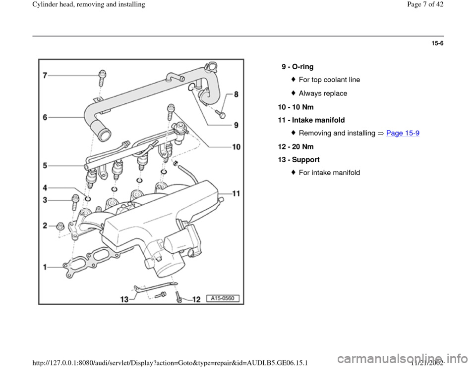
Fig. 1 Check cylinder head for distortion.
- Use knife edge, straightedge and feeler gauge to measure at several
points.
Max. permissible distortion: 0.1 mm
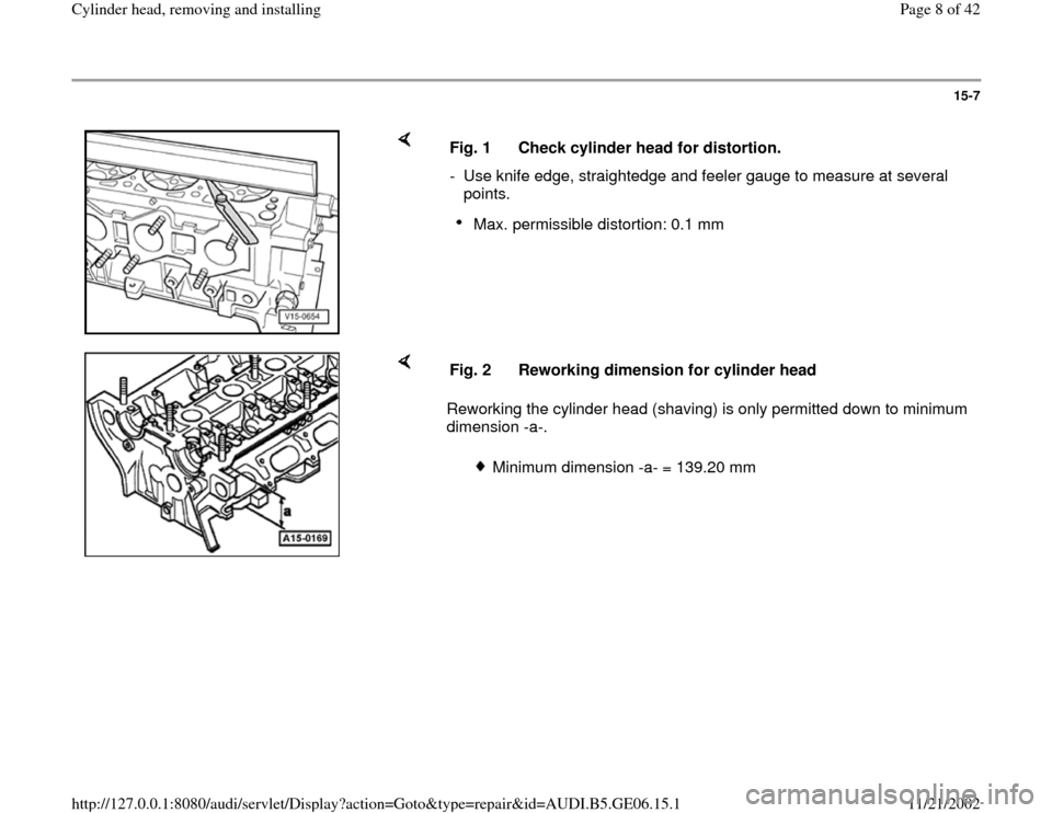
Reworking the cylinder head (shaving) is only permitted down to minimum
dimension -a-. Fig. 2 Reworking dimension for cylinder head
Minimum dimension -a- = 139.20 mm
Pa
ge 8 of 42 C
ylinder head, removin
g and installin
g
11/21/2002 htt
p://127.0.0.1:8080/audi/servlet/Dis
play?action=Goto&t
yp
e=re
pair&id=AUDI.B5.GE06.15.1
Page 9 of 42
15-8
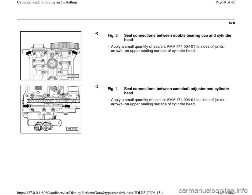
Fig. 3 Seal connections between double bearing cap and cylinder
head
- Apply a small quantity of sealant AMV 174 004 01 to sides of joints -
arrows- on upper sealing surface of cylinder head.
Fig. 4 Seal connections between camshaft adjuster and cylinder
head
- Apply a small quantity of sealant AMV 174 004 01 to sides of joints -
arrows- on upper sealing surface of cylinder head.
Pa
ge 9 of 42 C
ylinder head, removin
g and installin
g
11/21/2002 htt
p://127.0.0.1:8080/audi/servlet/Dis
play?action=Goto&t
yp
e=re
pair&id=AUDI.B5.GE06.15.1
Page 10 of 42
15-9
Intake manifold, removing and installing
Removing
- Observe or obtain radio anti-theft code on
vehicles with coded radio.
- Disconnect Ground strap at battery with ignition
switched off.
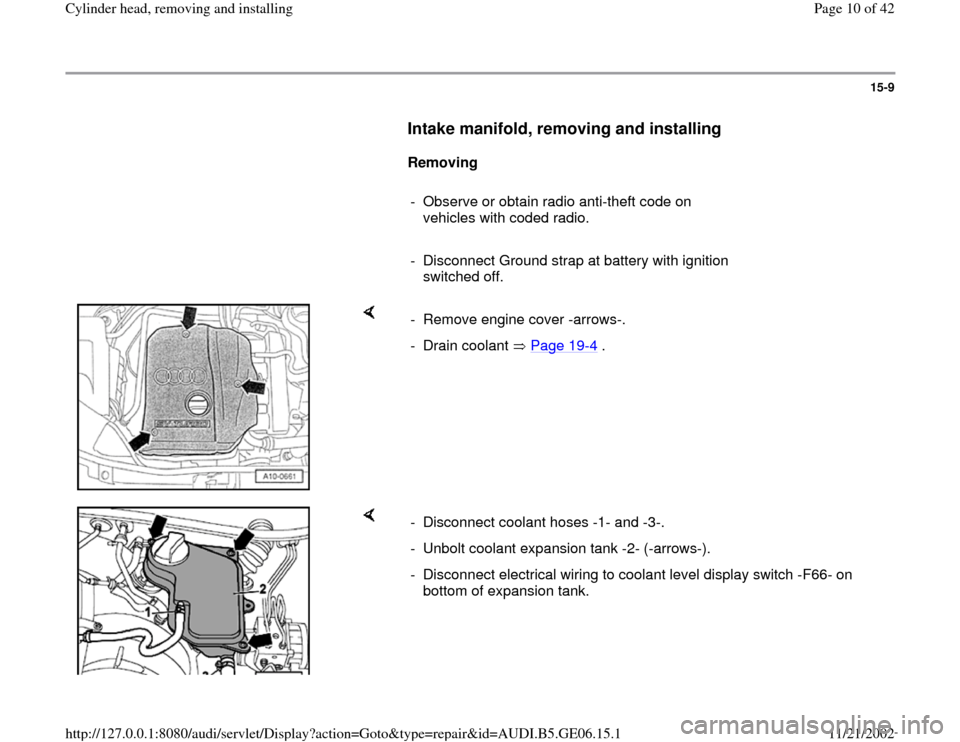
- Remove engine cover -arrows-.
- Drain coolant Page 19
-4 .
- Disconnect coolant hoses -1- and -3-.
- Unbolt coolant expansion tank -2- (-arrows-).
- Disconnect electrical wiring to coolant level display switch -F66- on
bottom of expansion tank.
Pa
ge 10 of 42 C
ylinder head, removin
g and installin
g
11/21/2002 htt
p://127.0.0.1:8080/audi/servlet/Dis
play?action=Goto&t
yp
e=re
pair&id=AUDI.B5.GE06.15.1
Trending: manual radio set, wiring, engine oil, coolant temperature, fuel pressure, check oil, timing belt
