fuel pump AUDI A4 1998 B5 / 1.G AWM Engine Motronic Injection System Servicing Workshop Manual
[x] Cancel search | Manufacturer: AUDI, Model Year: 1998, Model line: A4, Model: AUDI A4 1998 B5 / 1.GPages: 79, PDF Size: 1.04 MB
Page 15 of 79
24-13
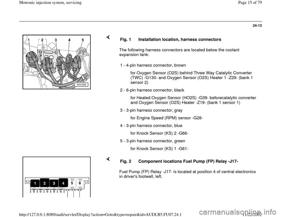
The following harness connectors are located below the coolant
expansion tank: Fig. 1 Installation location, harness connectors
1 - 4-pin harness connector, brown
for Oxygen Sensor (O2S) behind Three Way Catalytic Converter
(TWC) -G130- and Oxygen Sensor (O2S) Heater 1 -Z29- (bank 1
sensor 2)
2 - 6-pin harness connector, black
for Heated Oxygen Sensor (HO2S) -G39- beforecatalytic converter
and Oxygen Sensor (O2S) Heater -Z19- (bank 1 sensor 1)
3 - 3-pin harness connector, gray
for Engine Speed (RPM) sensor -G28-
4 - 3-pin harness connector, blue
for Knock Sensor (KS) 2 -G66-
5 - 3-pin harness connector, green
for Knock Sensor (KS) 1 -G61-
Fuel Pump (FP) Relay -J17- is located at position 4 of central electronics
in driver's footwell, left. Fig. 2 Component locations Fuel Pump (FP) Relay -J17-
Pa
ge 15 of 79 Motronic in
jection s
ystem, servicin
g
11/22/2002 htt
p://127.0.0.1:8080/audi/servlet/Dis
play?action=Goto&t
yp
e=re
pair&id=AUDI.B5.FU07.24.1
Page 35 of 79
24-32
System pressure, fuel pressure
regulator and residual pressure,
checking
Note:
Fuel pressure regulator regulates fuel pressure
according to intake manifold pressure. This
ensures that the pressure drop at the fuel
injectors remains the same for each speed and
load range of the engine.
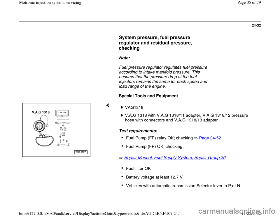
Special Tools and Equipment
Test requirements:
Repair Manual, Fuel Supply System, Repair Group 20
VAG1318V.A.G 1318 with V.A.G 1318/11 adapter, V.A.G 1318/12 pressure
hose with connectors and V.A.G 1318/13 adapter Fuel Pump (FP) relay OK; checking Page 24
-52
.
Fuel Pump (FP) OK, checking: Fuel filter OK Battery voltage at least 12.7 V Vehicles with automatic transmission Selector lever in P or N.
Pa
ge 35 of 79 Motronic in
jection s
ystem, servicin
g
11/22/2002 htt
p://127.0.0.1:8080/audi/servlet/Dis
play?action=Goto&t
yp
e=re
pair&id=AUDI.B5.FU07.24.1
Page 38 of 79
24-35
If residual pressure sinks below 2.5 bar positive
pressure:
- Start engine and let run at idle.
If pressure does not drop now:
If pressure drops again:
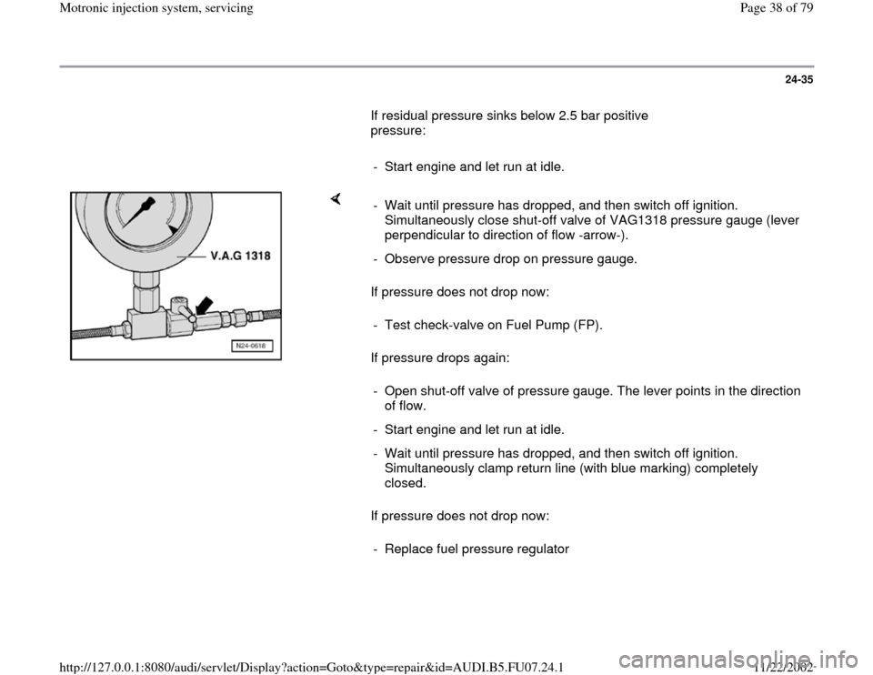
If pressure does not drop now: - Wait until pressure has dropped, and then switch off ignition.
Simultaneously close shut-off valve of VAG1318 pressure gauge (lever
perpendicular to direction of flow -arrow-).
- Observe pressure drop on pressure gauge.
- Test check-valve on Fuel Pump (FP).
- Open shut-off valve of pressure gauge. The lever points in the direction
of flow.
- Start engine and let run at idle.
- Wait until pressure has dropped, and then switch off ignition.
Simultaneously clamp return line (with blue marking) completely
closed.
- Replace fuel pressure regulator
Pa
ge 38 of 79 Motronic in
jection s
ystem, servicin
g
11/22/2002 htt
p://127.0.0.1:8080/audi/servlet/Dis
play?action=Goto&t
yp
e=re
pair&id=AUDI.B5.FU07.24.1
Page 42 of 79
24-39
Checking voltage supply
Test requirements:
Fuse for fuel injectors OK
Electrical Wiring Diagrams, Troubleshooting &
Component Locations
Fuel Pump (FP) relay OK; checking Page 24
-52
.
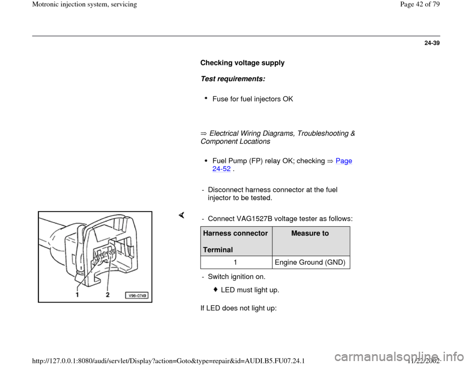
- Disconnect harness connector at the fuel
injector to be tested.
If LED does not light up: - Connect VAG1527B voltage tester as follows:Harness connector
Terminal
Measure to
1 Engine Ground (GND)
- Switch ignition on.
LED must light up.
Pa
ge 42 of 79 Motronic in
jection s
ystem, servicin
g
11/22/2002 htt
p://127.0.0.1:8080/audi/servlet/Dis
play?action=Goto&t
yp
e=re
pair&id=AUDI.B5.FU07.24.1
Page 53 of 79
24-49
Test requirement:
Fuel pressure OK, checking Page 24
-32
.
Test sequence
- Remove fuel distributor including fuel injectors
from intake manifold Page 24
-45
. Fuel lines
remain connected.
- Connect VAG1598/31 test box at wiring harness
to Engine Control Module (ECM), do not connect
ECM Page 24
-19
.
Checking Proper Seal
- Bridge terminals 1 and 65 at test box using wires
from VAG1594A adapter test kit.
- Switch ignition on.
Fuel Pump (FP) must run.
- Check proper seal of fuel injectors (visual
inspection). With Fuel Pump (FP) running, only 1
to 2 drops per minute may drip out per injector.
-
If fuel loss is greater, stop Fuel Pump (FP) from
Pa
ge 53 of 79 Motronic in
jection s
ystem, servicin
g
11/22/2002 htt
p://127.0.0.1:8080/audi/servlet/Dis
play?action=Goto&t
yp
e=re
pair&id=AUDI.B5.FU07.24.1
Page 55 of 79

24-50
Checking Injection Quantity
- Insert fuel injector to be tested in a measuring
glass from VAG1602 injection quantity test
device.
- Connect one terminal of fuel injector to engine Ground (GND) using an
adapter cable and an alligator clip from VAG1594A connector test kit.
- Connect the second terminal of fuel injector to B+ using VAG1348/3A
remote control, VAG1348/3-2 adapter cable and assisting cable.
- Bridge terminals 1 and 65 at test box using wires from VAG1594A
adapter test kit.
- Bridge terminals 1 and 65 at test box using wires from VAG1594A
adapter test kit.
- Switch ignition on.
Fuel Pump (FP) must run.
- Activate VAG1348/3A remote control for 30 seconds.
- Perform measurement on all fuel injectors.
Pa
ge 55 of 79 Motronic in
jection s
ystem, servicin
g
11/22/2002 htt
p://127.0.0.1:8080/audi/servlet/Dis
play?action=Goto&t
yp
e=re
pair&id=AUDI.B5.FU07.24.1
Page 56 of 79

24-51
- After all four fuel injectors have been activated,
place measuring glasses on an even surface.
Specified value for each fuel injector: 135
10 ml
- If measured value of one or more fuel injectors
is outside of specified range, switch Fuel Pump
(FP) off (switch ignition off) and replace faulty
fuel injector Page 24
-45
.
- If the measured values of all fuel injectors are
outside the specified range, check fuel pressure
Page 24
-32
.
Note:
Also check spray pattern when checking injection
quantity. Spray pattern must be the same for all
injectors
- Install fuel injectors together with fuel distributor
Page 24
-46
.
Pa
ge 56 of 79 Motronic in
jection s
ystem, servicin
g
11/22/2002 htt
p://127.0.0.1:8080/audi/servlet/Dis
play?action=Goto&t
yp
e=re
pair&id=AUDI.B5.FU07.24.1
Page 57 of 79
24-52
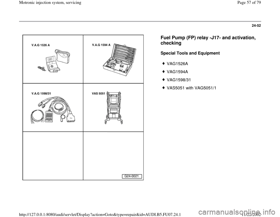
Fuel Pump (FP) relay -J17- and activation,
checking
Special Tools and Equipment
VAG1526A
VAG1594A
VAG1598/31
VAS5051 with VAG5051/1
Pa
ge 57 of 79 Motronic in
jection s
ystem, servicin
g
11/22/2002 htt
p://127.0.0.1:8080/audi/servlet/Dis
play?action=Goto&t
yp
e=re
pair&id=AUDI.B5.FU07.24.1
Page 58 of 79
24-53
Component location Overview of component
locations Page 24
-5
Voltage is supplied to the Fuel Pump (FP) and
several components of the injection system via
the Fuel Pump (FP) relay -J17-.
Engine must be turning for Fuel Pump (FP) relay
-J17- to close. This means that the relay does
not receive Ground (GND) (via ECM) until the
ECM recognizes RPM signals.
Test requirement:
Battery voltage at least 12.7 V
Function test of Fuel Pump (FP) relay
- Remove driver-side storage compartment.
Repair Manual, Body Interior, Repair Group
68
- Connect VAS5051 tester Page 01
-7 and
select vehicle system "01 - Engine electronics".
Ignition must remain switched on for this.
-
Initiate output Diagnostic Test Mode (DTM)
Page 01
-51
and activate Evaporative Emission
Pa
ge 58 of 79 Motronic in
jection s
ystem, servicin
g
11/22/2002 htt
p://127.0.0.1:8080/audi/servlet/Dis
play?action=Goto&t
yp
e=re
pair&id=AUDI.B5.FU07.24.1
Page 60 of 79
24-54
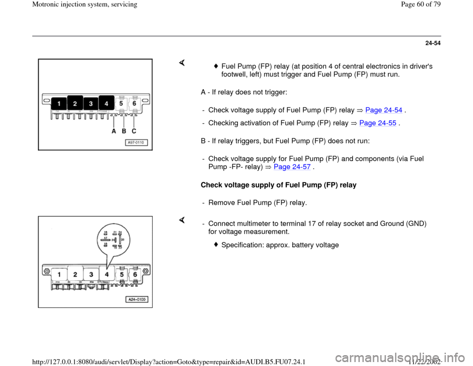
A - If relay does not trigger:
B - If relay triggers, but Fuel Pump (FP) does not run:
Check voltage supply of Fuel Pump (FP) relay
Fuel Pump (FP) relay (at position 4 of central electronics in driver's
footwell, left) must trigger and Fuel Pump (FP) must run.
- Check voltage supply of Fuel Pump (FP) relay Page 24
-54
.
- Checking activation of Fuel Pump (FP) relay Page 24
-55
.
- Check voltage supply for Fuel Pump (FP) and components (via Fuel
Pump -FP- relay) Page 24
-57
.
- Remove Fuel Pump (FP) relay.
- Connect multimeter to terminal 17 of relay socket and Ground (GND)
for voltage measurement.
Specification: approx. battery voltage
Pa
ge 60 of 79 Motronic in
jection s
ystem, servicin
g
11/22/2002 htt
p://127.0.0.1:8080/audi/servlet/Dis
play?action=Goto&t
yp
e=re
pair&id=AUDI.B5.FU07.24.1