battery AUDI A4 1998 B5 / 1.G Brakes Output DTM 03 Workshop Manual
[x] Cancel search | Manufacturer: AUDI, Model Year: 1998, Model line: A4, Model: AUDI A4 1998 B5 / 1.GPages: 66, PDF Size: 0.34 MB
Page 5 of 66

01-152
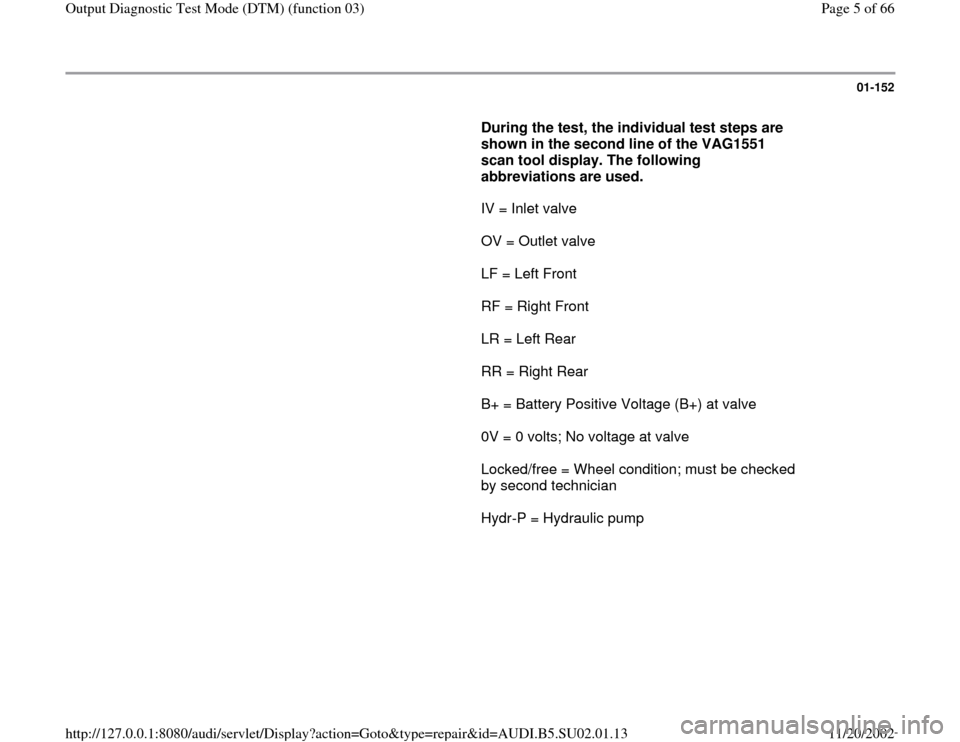
During the test, the individual test steps are
shown in the second line of the VAG1551
scan tool display. The following
abbreviations are used.
IV = Inlet valve
OV = Outlet valve
LF = Left Front
RF = Right Front
LR = Left Rear
RR = Right Rear
B+ = Battery Positive Voltage (B+) at valve
0V = 0 volts; No voltage at valve
Locked/free = Wheel condition; must be checked
by second technician
Hydr-P = Hydraulic pump
Pa
ge 5 of 66 Out
put Dia
gnostic Test Mode
(DTM
) (function 03
)
11/20/2002 htt
p://127.0.0.1:8080/audi/servlet/Dis
play?action=Goto&t
yp
e=re
pair&id=AUDI.B5.SU02.01.13
Page 25 of 66

01-171
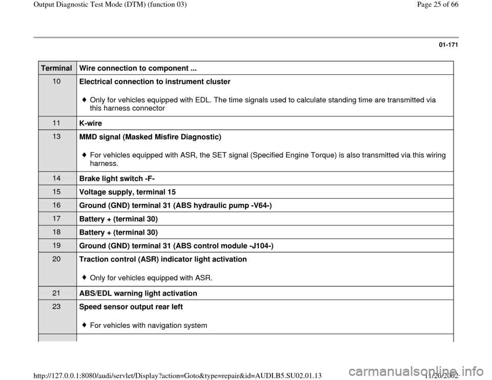
Terminal
Wire connection to component ...
10
Electrical connection to instrument cluster
Only for vehicles equipped with EDL. The time signals used to calculate standing time are transmitted via
this harness connector
11
K-wire 13
MMD signal (Masked Misfire Diagnostic)
For vehicles equipped with ASR, the SET signal (Specified Engine Torque) is also transmitted via this wiring
harness.
14
Brake light switch -F- 15
Voltage supply, terminal 15 16
Ground (GND) terminal 31 (ABS hydraulic pump -V64-) 17
Battery + (terminal 30) 18
Battery + (terminal 30) 19
Ground (GND) terminal 31 (ABS control module -J104-) 20
Traction control (ASR) indicator light activation
Only for vehicles equipped with ASR.
21
ABS/EDL warning light activation 23
Speed sensor output rear left
For vehicles with navigation system
Pa
ge 25 of 66 Out
put Dia
gnostic Test Mode
(DTM
) (function 03
)
11/20/2002 htt
p://127.0.0.1:8080/audi/servlet/Dis
play?action=Goto&t
yp
e=re
pair&id=AUDI.B5.SU02.01.13
Page 57 of 66

01-197
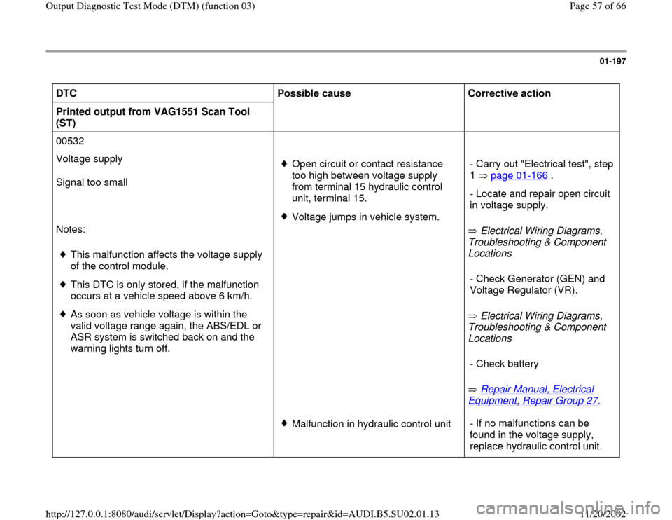
DTC
Possible cause
Corrective action
Printed output from VAG1551 Scan Tool
(ST)
00532
Voltage supply
Signal too small
Notes:
This malfunction affects the voltage supply
of the control module.
This DTC is only stored, if the malfunction
occurs at a vehicle speed above 6 km/h.
As soon as vehicle voltage is within the
valid voltage range again, the ABS/EDL or
ASR system is switched back on and the
warning lights turn off.
Open circuit or contact resistance
too high between voltage supply
from terminal 15 hydraulic control
unit, terminal 15. Voltage jumps in vehicle system.
Electrical Wiring Diagrams,
Troubleshooting & Component
Locations
Electrical Wiring Diagrams,
Troubleshooting & Component
Locations
Repair Manual, Electrical
Equipment, Repair Group 27.
- Carry out "Electrical test", step
1 page 01
-166
.
- Locate and repair open circuit
in voltage supply. - Check Generator (GEN) and
Voltage Regulator (VR). - Check battery
Malfunction in hydraulic control unit- If no malfunctions can be
found in the voltage supply,
replace hydraulic control unit.
Pa
ge 57 of 66 Out
put Dia
gnostic Test Mode
(DTM
) (function 03
)
11/20/2002 htt
p://127.0.0.1:8080/audi/servlet/Dis
play?action=Goto&t
yp
e=re
pair&id=AUDI.B5.SU02.01.13
Page 64 of 66

01-204
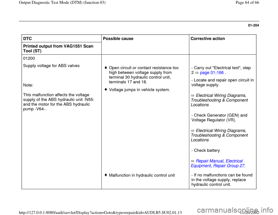
DTC
Possible cause
Corrective action
Printed output from VAG1551 Scan
Tool (ST)
01200
Supply voltage for ABS valves
Note:
This malfunction affects the voltage
supply of the ABS hydraulic unit -N55-
and the motor for the ABS hydraulic
pump -V64-.
Open circuit or contact resistance too
high between voltage supply from
terminal 30 hydraulic control unit,
terminals 17 and 18. Voltage jumps in vehicle system.
Electrical Wiring Diagrams,
Troubleshooting & Component
Locations
Electrical Wiring Diagrams,
Troubleshooting & Component
Locations
Repair Manual, Electrical
Equipment, Repair Group 27.
- Carry out "Electrical test", step
2 page 01
-166
.
- Locate and repair open circuit in
voltage supply. - Check Generator (GEN) and
Voltage Regulator (VR). - Check battery
Malfunction in hydraulic control unit- If no malfunctions can be found
in the voltage supply, replace
hydraulic control unit.
Pa
ge 64 of 66 Out
put Dia
gnostic Test Mode
(DTM
) (function 03
)
11/20/2002 htt
p://127.0.0.1:8080/audi/servlet/Dis
play?action=Goto&t
yp
e=re
pair&id=AUDI.B5.SU02.01.13