wheel AUDI A4 1998 B5 / 1.G Suspension Rear Axle Front Wheel Drive Workshop Manual
[x] Cancel search | Manufacturer: AUDI, Model Year: 1998, Model line: A4, Model: AUDI A4 1998 B5 / 1.GPages: 26, PDF Size: 0.49 MB
Page 1 of 26
42-1
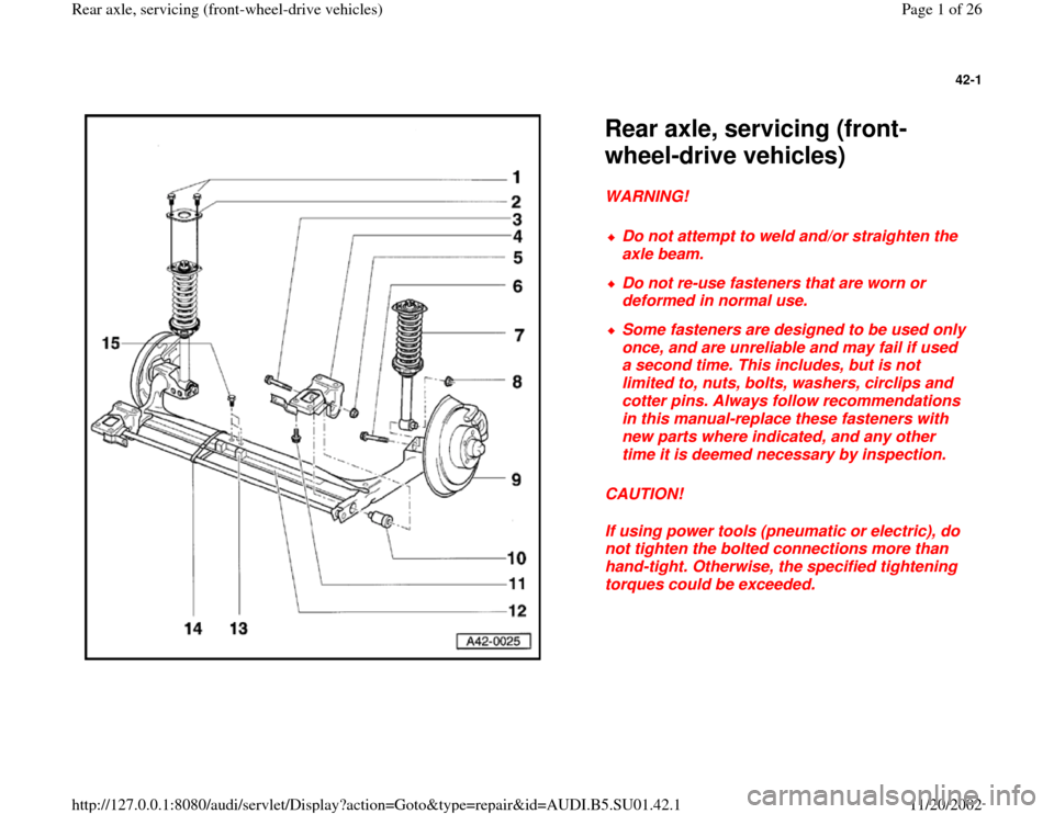
Rear axle, servicing (front-
wheel-drive vehicles) WARNING!
CAUTION!
If using power tools (pneumatic or electric), do
not tighten the bolted connections more than
hand-tight. Otherwise, the specified tightening
torques could be exceeded.
Do not attempt to weld and/or straighten the
axle beam.
Do not re-use fasteners that are worn or
deformed in normal use.
Some fasteners are designed to be used only
once, and are unreliable and may fail if used
a second time. This includes, but is not
limited to, nuts, bolts, washers, circlips and
cotter pins. Always follow recommendations
in this manual-replace these fasteners with
new parts where indicated, and any other
time it is deemed necessary by inspection.
Pa
ge 1 of 26 Rear axle, servicin
g (front-wheel-drive vehicles
)
11/20/2002 htt
p://127.0.0.1:8080/audi/servlet/Dis
play?action=Goto&t
yp
e=re
pair&id=AUDI.B5.SU01.42.1
Page 2 of 26
42-2
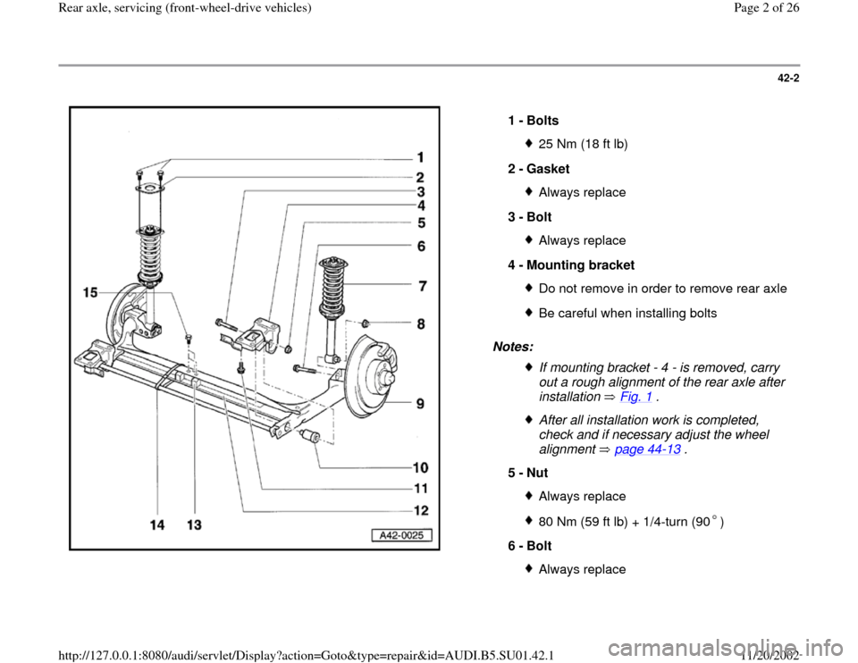
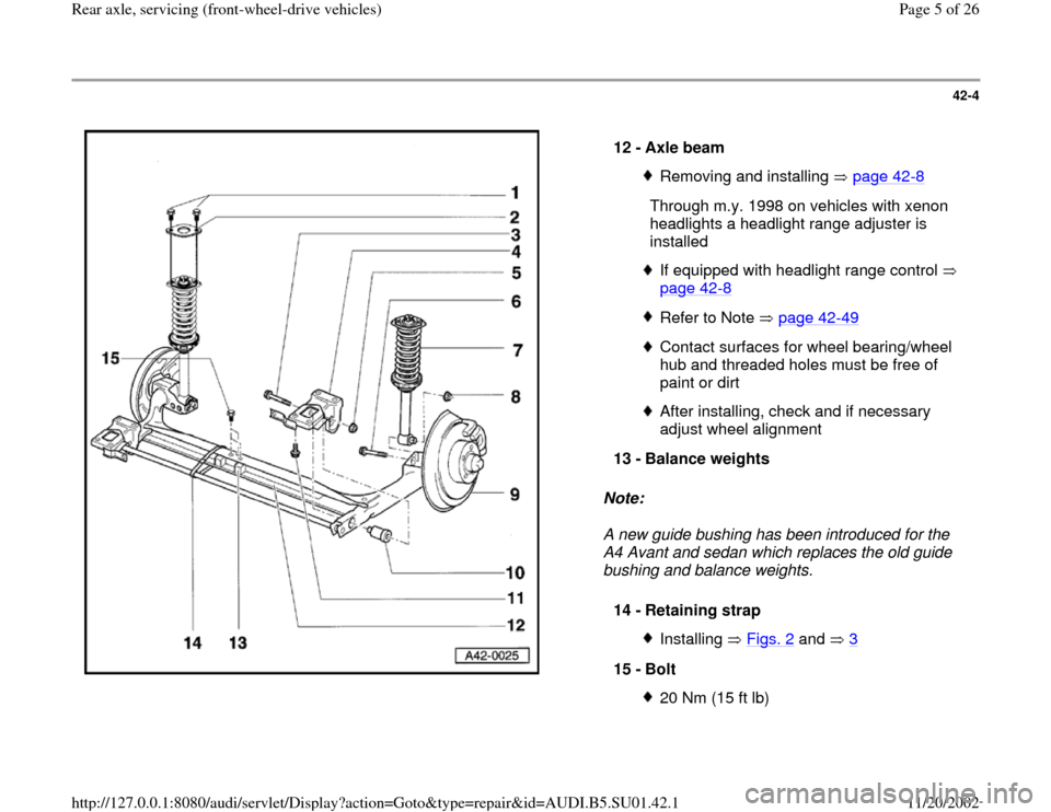
Notes: 1 -
Bolts
25 Nm (18 ft lb)
2 -
Gasket Always replace
3 -
Bolt Always replace
4 -
Mounting bracket Do not remove in order to remove rear axleBe careful when installing boltsIf mounting bracket - 4 - is removed, carry
out a rough alignment of the rear axle after
installation Fig. 1
.
After all installation work is completed,
check and if necessary adjust the wheel
alignment page 44
-13
.
5 -
Nut
Always replace80 Nm (59 ft lb) + 1/4-turn (90 )
6 -
Bolt
Always replace
Pa
ge 2 of 26 Rear axle, servicin
g (front-wheel-drive vehicles
)
11/20/2002 htt
p://127.0.0.1:8080/audi/servlet/Dis
play?action=Goto&t
yp
e=re
pair&id=AUDI.B5.SU01.42.1
Page 3 of 26
50 Nm (37 ft lb) + 1/4-turn (90 )
Pa
ge 3 of 26 Rear axle, servicin
g (front-wheel-drive vehicles
)
11/20/2002 htt
p://127.0.0.1:8080/audi/servlet/Dis
play?action=Goto&t
yp
e=re
pair&id=AUDI.B5.SU01.42.1
Page 4 of 26
42-3
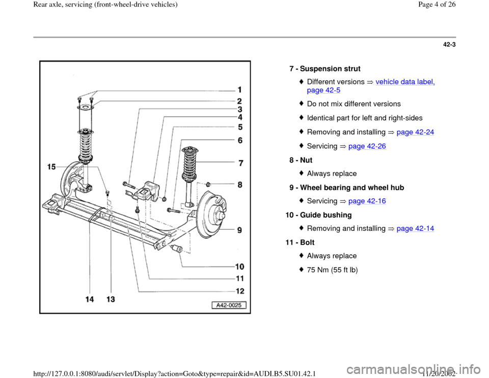
7 -
Suspension strut
Different versions vehicle data label, page 42
-5
Do not mix different versionsIdentical part for left and right-sidesRemoving and installing page 42
-24
Servicing page 42
-26
8 -
Nut
Always replace
9 -
Wheel bearing and wheel hub Servicing page 42
-16
10 -
Guide bushing
Removing and installing page 42
-14
11 -
Bolt
Always replace75 Nm (55 ft lb)
Pa
ge 4 of 26 Rear axle, servicin
g (front-wheel-drive vehicles
)
11/20/2002 htt
p://127.0.0.1:8080/audi/servlet/Dis
play?action=Goto&t
yp
e=re
pair&id=AUDI.B5.SU01.42.1
Page 5 of 26
42-4
Note:
A new guide bushing has been introduced for the
A4 Avant and sedan which replaces the old guide
bushing and balance weights. 12 -
Axle beam
Removing and installing page 42
-8
Through m.y. 1998 on vehicles with xenon
headlights a headlight range adjuster is
installed
If equipped with headlight range control
page 42
-8
Refer to Note page 42
-49
Contact surfaces for wheel bearing/wheel
hub and threaded holes must be free of
paint or dirt After installing, check and if necessary
adjust wheel alignment
13 -
Balance weights
14 -
Retaining strap Installing Figs. 2
and 3
15 -
Bolt
20 Nm (15 ft lb)
Pa
ge 5 of 26 Rear axle, servicin
g (front-wheel-drive vehicles
)
11/20/2002 htt
p://127.0.0.1:8080/audi/servlet/Dis
play?action=Goto&t
yp
e=re
pair&id=AUDI.B5.SU01.42.1
Page 6 of 26
42-5
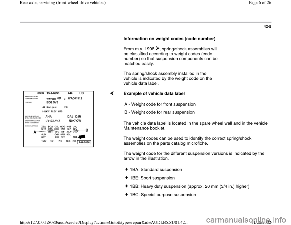
Information on weight codes (code number)
From m.y. 1998 , spring/shock assemblies will
be classified according to weight codes (code
number) so that suspension components can be
matched easily. The spring/shock assembly installed in the
vehicle is indicated by the weight code on the
vehicle data label.
Example of vehicle data label
The vehicle data label is located in the spare wheel well and in the vehicle
Maintenance booklet.
The weight codes can be used to identify the correct spring/shock
assemblies on the parts catalog microfiche.
The weight code for the different suspension versions is indicated by the
arrow in the illustration. A - Weight code for front suspension
B - Weight code for rear suspension
1BA: Standard suspension1BE: Sport suspension 1BB: Heavy duty suspension (approx. 20 mm (3/4 in.) higher)1BC: Special purpose suspension
Pa
ge 6 of 26 Rear axle, servicin
g (front-wheel-drive vehicles
)
11/20/2002 htt
p://127.0.0.1:8080/audi/servlet/Dis
play?action=Goto&t
yp
e=re
pair&id=AUDI.B5.SU01.42.1
Page 7 of 26
1BD: Sport suspension, Audi S41BH: USA
Pa
ge 7 of 26 Rear axle, servicin
g (front-wheel-drive vehicles
)
11/20/2002 htt
p://127.0.0.1:8080/audi/servlet/Dis
play?action=Goto&t
yp
e=re
pair&id=AUDI.B5.SU01.42.1
Page 8 of 26
42-6
1BT: Heavy duty suspension (approx. 7 mm or
1/4 in. higher)
1BP: Heavy duty suspension (same ride height
as 1BA but with limited bump)
Checking wheel alignment page 44
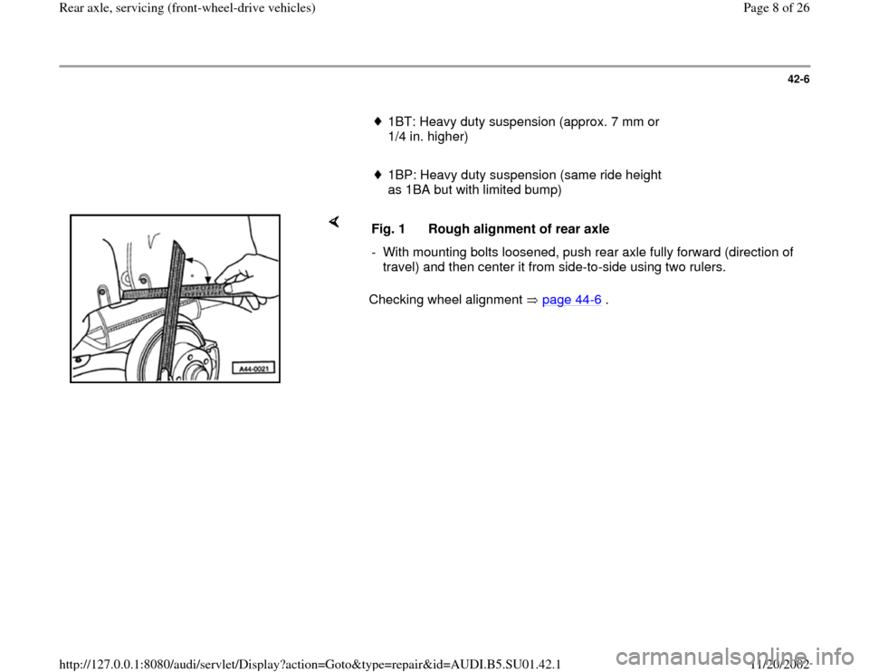
-6 . Fig. 1 Rough alignment of rear axle
- With mounting bolts loosened, push rear axle fully forward (direction of
travel) and then center it from side-to-side using two rulers.
Pa
ge 8 of 26 Rear axle, servicin
g (front-wheel-drive vehicles
)
11/20/2002 htt
p://127.0.0.1:8080/audi/servlet/Dis
play?action=Goto&t
yp
e=re
pair&id=AUDI.B5.SU01.42.1
Page 9 of 26
42-7
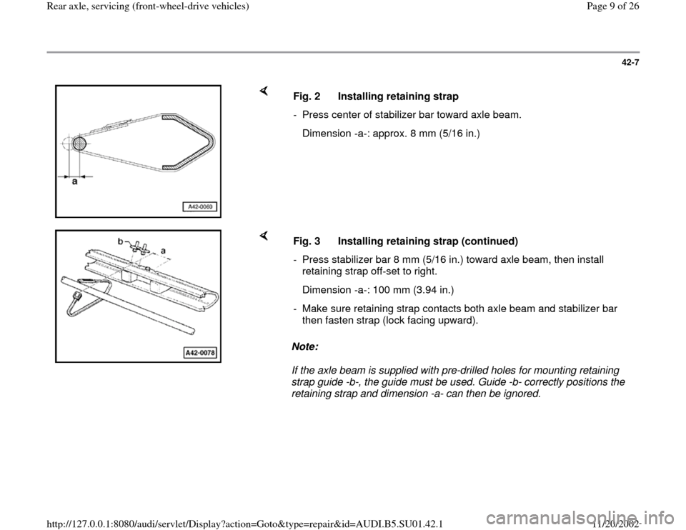
Fig. 2 Installing retaining strap
- Press center of stabilizer bar toward axle beam.
Dimension -a-: approx. 8 mm (5/16 in.)
Note:
If the axle beam is supplied with pre-drilled holes for mounting retaining
strap guide -b-, the guide must be used. Guide -b- correctly positions the
retaining strap and dimension -a- can then be ignored. Fig. 3 Installing retaining strap (continued)
- Press stabilizer bar 8 mm (5/16 in.) toward axle beam, then install
retaining strap off-set to right.
Dimension -a-: 100 mm (3.94 in.)
- Make sure retaining strap contacts both axle beam and stabilizer bar
then fasten strap (lock facing upward).
Pa
ge 9 of 26 Rear axle, servicin
g (front-wheel-drive vehicles
)
11/20/2002 htt
p://127.0.0.1:8080/audi/servlet/Dis
play?action=Goto&t
yp
e=re
pair&id=AUDI.B5.SU01.42.1
Page 10 of 26
42-8
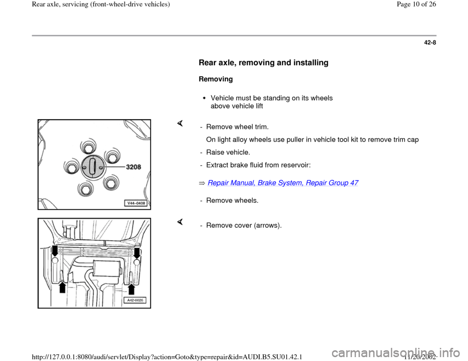
Rear axle, removing and installing
Removing
Vehicle must be standing on its wheels
above vehicle lift
Repair Manual, Brake System, Repair Group 47
- Remove wheel trim.
On light alloy wheels use puller in vehicle tool kit to remove trim cap
- Raise vehicle.
- Extract brake fluid from reservoir:
- Remove wheels.
- Remove cover (arrows).
Pa
ge 10 of 26 Rear axle, servicin
g (front-wheel-drive vehicles
)
11/20/2002 htt
p://127.0.0.1:8080/audi/servlet/Dis
play?action=Goto&t
yp
e=re
pair&id=AUDI.B5.SU01.42.1