AUDI A4 1999 B5 / 1.G AFC Engine Auxiliary Input Signals Checking Workshop Manual
Manufacturer: AUDI, Model Year: 1999,
Model line: A4,
Model: AUDI A4 1999 B5 / 1.G
Pages: 37, PDF Size: 0.15 MB
AUDI A4 1999 B5 / 1.G AFC Engine Auxiliary Input Signals Checking Workshop Manual
A4 1999 B5 / 1.G
AUDI
AUDI
https://www.carmanualsonline.info/img/6/1005/w960_1005-0.png
AUDI A4 1999 B5 / 1.G AFC Engine Auxiliary Input Signals Checking Workshop Manual
Trending: traction control, manual transmission, light, brake light, instrument cluster, brake, air condition
Page 1 of 37
24-88
Auxiliary input signals,
checking
Rear window defroster signal, checking
Requirement
Engine Control Module (ECM) coding OK
page 01
-247
.
Checking
- Using VAG 1551 scan tool, select "Read
Measuring Value Block" function 08, display
group 004, display field 4 page 01
-249
.
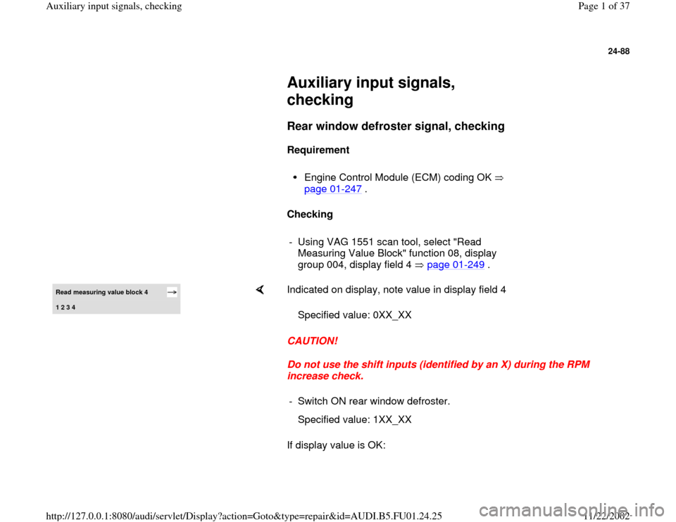
Read measuring value block 4 1 2 3 4
Indicated on display, note value in display field 4
CAUTION!
Do not use the shift inputs (identified by an X) during the RPM
increase check.
If display value is OK: Specified value: 0XX_XX
- Switch ON rear window defroster.
Specified value: 1XX_XX
Pa
ge 1 of 37 Auxiliar
y in
put si
gnals, checkin
g
11/22/2002 htt
p://127.0.0.1:8080/audi/servlet/Dis
play?action=Goto&t
yp
e=re
pair&id=AUDI.B5.FU01.24.25
Page 2 of 37
-
Press button.- Select "End Output" function 06.
- Press -Q- button to confirm input.
Pa
ge 2 of 37 Auxiliar
y in
put si
gnals, checkin
g
11/22/2002 htt
p://127.0.0.1:8080/audi/servlet/Dis
play?action=Goto&t
yp
e=re
pair&id=AUDI.B5.FU01.24.25
Page 3 of 37
24-89
If display value does not change:
- Switch ignition OFF and connect VAG 1598/19
test box to ECM harness connector page 01
-
255
.
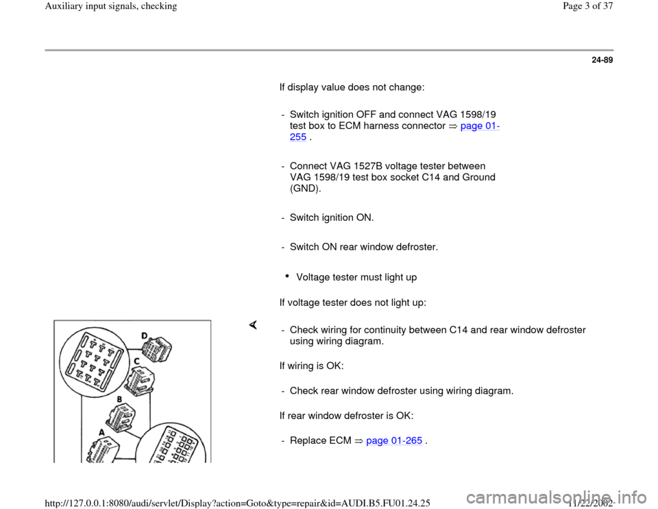
- Connect VAG 1527B voltage tester between
VAG 1598/19 test box socket C14 and Ground
(GND).
- Switch ignition ON.
- Switch ON rear window defroster.
Voltage tester must light up
If voltage tester does not light up:
If wiring is OK:
If rear window defroster is OK: - Check wiring for continuity between C14 and rear window defroster
using wiring diagram.
- Check rear window defroster using wiring diagram.
- Replace ECM page 01
-265
.
Pa
ge 3 of 37 Auxiliar
y in
put si
gnals, checkin
g
11/22/2002 htt
p://127.0.0.1:8080/audi/servlet/Dis
play?action=Goto&t
yp
e=re
pair&id=AUDI.B5.FU01.24.25
Page 4 of 37
24-90
A/C compressor shut-off signal,
checking
Note:
The A/C compressor is switched off during
acceleration by the Engine Control Module
(ECM) and at wide open throttle by the
Transmission Control Module (TCM) via the
kickdown switch.
A/C compressor shut-off is bi-directional ("in"and
"out").
IN: Shortly before switching the A/C
compressor on, voltage is applied to the ECM
which causes the Idle Air Control (IAC) valve to
open a little more to adjust to the higher load.
OUT: When accelerating from a standstill
position and at lower speed, the A/C
compressor is shut off for approx. 12 seconds
via control by the ECM. If the accelerator pedal
is released early enough, the duration is
reduced to a minimal 3 seconds.
Checking requirements
A/C function OK
Pa
ge 4 of 37 Auxiliar
y in
put si
gnals, checkin
g
11/22/2002 htt
p://127.0.0.1:8080/audi/servlet/Dis
play?action=Goto&t
yp
e=re
pair&id=AUDI.B5.FU01.24.25
Page 5 of 37
No malfunctions stored in DTC memory
Vehicle at room temperature; above 15 C
(59 F)
Pa
ge 5 of 37 Auxiliar
y in
put si
gnals, checkin
g
11/22/2002 htt
p://127.0.0.1:8080/audi/servlet/Dis
play?action=Goto&t
yp
e=re
pair&id=AUDI.B5.FU01.24.25
Page 6 of 37
24-91
Checking
- Start engine and let idle.
- Switch A/C on, push "AUTO" button, set
temperature to "LO" and blower speed to "HI".
A/C compressor symbol must light up and
A/C must run.
- Using VAG 1551 scan tool, select "Basic
Setting" function 04, display group 004 page 01
-150
.
A/C compressor must stop (visual check)
If the A/C compressor does not shut off:
- Switch A/C off (press "minus" button for fresh air
blower in A/C control head repeatedly, until all
indicators are off).
Continue to let engine run in idle.
- Using VAG 1551 scan tool, select "Read
Measuring Value Block" function 08, display
group 004.
Pa
ge 6 of 37 Auxiliar
y in
put si
gnals, checkin
g
11/22/2002 htt
p://127.0.0.1:8080/audi/servlet/Dis
play?action=Goto&t
yp
e=re
pair&id=AUDI.B5.FU01.24.25
Page 7 of 37
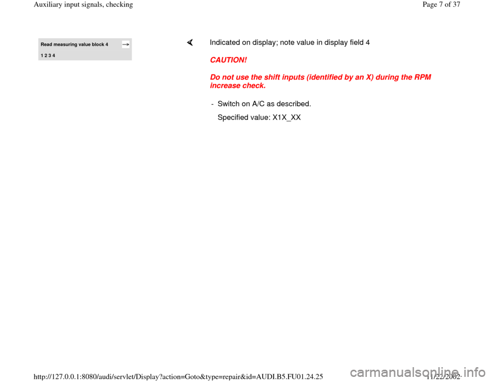
Read measuring value block 4 1 2 3 4
Indicated on display; note value in display field 4
CAUTION!
Do not use the shift inputs (identified by an X) during the RPM
increase check.
- Switch on A/C as described.
Specified value: X1X_XX
Pa
ge 7 of 37 Auxiliar
y in
put si
gnals, checkin
g
11/22/2002 htt
p://127.0.0.1:8080/audi/servlet/Dis
play?action=Goto&t
yp
e=re
pair&id=AUDI.B5.FU01.24.25
Page 8 of 37
24-92
If the specified values are obtained:
-
Press button.
- Select "End Output" function 06.
- Press -Q- button to confirm input.
If display value changes:
- The following display is possible: "A/C system
not switched on as described."
If the display value does not change, even
though the A/C system was switched on as
described:
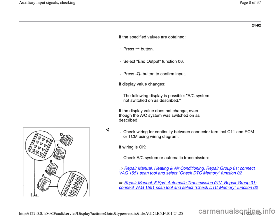
If wiring is OK:
Repair Manual, Heating & Air Conditioning, Repair Group 01; connect VAG 1551 scan tool and select "Check DTC Memory" function 02
Repair Manual, 5 Spd. Automatic Transmission 01V, Repair Group 01;
connect VAG 1551 scan tool and select "Check DTC Memory" function 02
- Check wiring for continuity between connector terminal C11 and ECM
or TCM using wiring diagram.
- Check A/C system or automatic transmission:
Pa
ge 8 of 37 Auxiliar
y in
put si
gnals, checkin
g
11/22/2002 htt
p://127.0.0.1:8080/audi/servlet/Dis
play?action=Goto&t
yp
e=re
pair&id=AUDI.B5.FU01.24.25
Page 9 of 37
Pa
ge 9 of 37 Auxiliar
y in
put si
gnals, checkin
g
11/22/2002 htt
p://127.0.0.1:8080/audi/servlet/Dis
play?action=Goto&t
yp
e=re
pair&id=AUDI.B5.FU01.24.25
Page 10 of 37
24-93
If X1X_XX is displayed:
- Briefly press accelerator pedal to apply wide
open throttle.
Display must switch briefly to X0X_XX, then
X1X_XX must appear again after several
seconds.
If display does not change as described:
- Check whether A/C compressor was shut off
while accelerator pedal was being pressed.
- Check A/C system or automatic transmission.
Repair Manual, Heating & Air Conditioning,
Repair Group 01; connect VAG 1551 scan tool and select "Check DTC Memory" function 02
Repair Manual, 5 Spd. Automatic
Transmission 01V, Repair Group 01
; connect
VAG 1551 scan tool and select "Check DTC
Memory" function 02
If the display does not change as described:
Pa
ge 10 of 37 Auxiliar
y in
put si
gnals, checkin
g
11/22/2002 htt
p://127.0.0.1:8080/audi/servlet/Dis
play?action=Goto&t
yp
e=re
pair&id=AUDI.B5.FU01.24.25
Trending: fuel, lock, instrument cluster, torque, light, wheel torque, turn signal
