fuel pump AUDI A4 1999 B5 / 1.G AFC Engine On Board Diagnostic Multiport Fuel Injection User Guide
[x] Cancel search | Manufacturer: AUDI, Model Year: 1999, Model line: A4, Model: AUDI A4 1999 B5 / 1.GPages: 366, PDF Size: 1.21 MB
Page 175 of 366
01-129
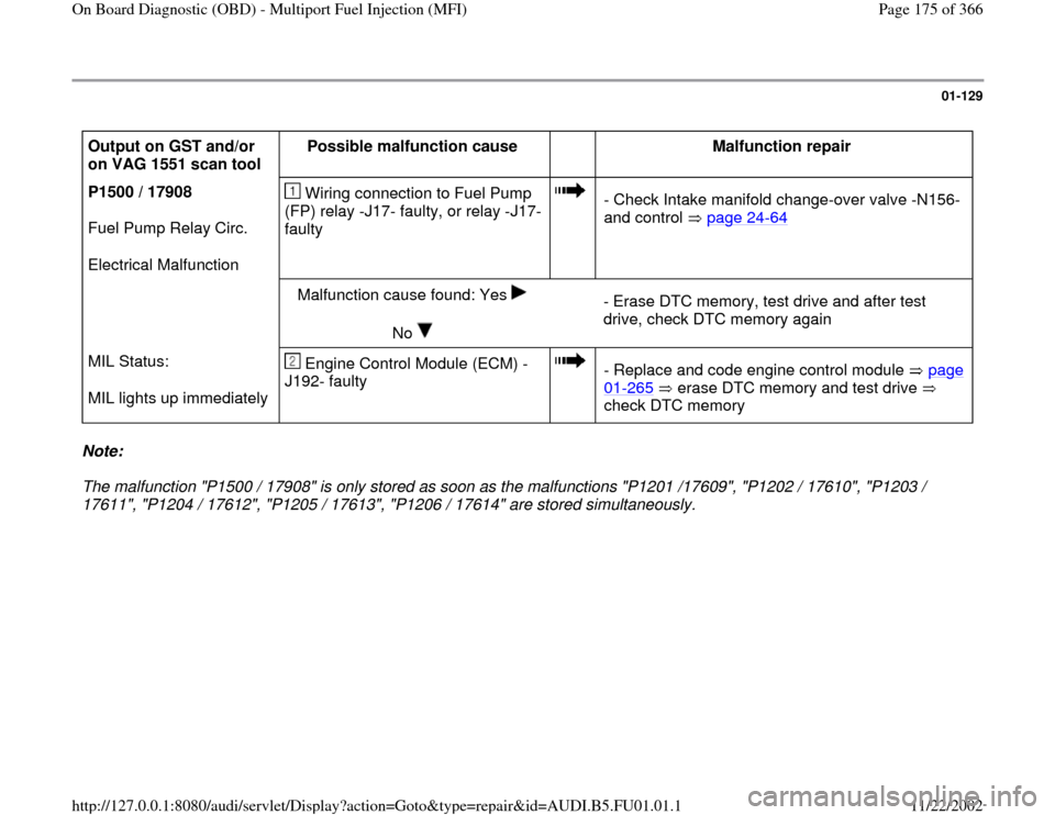
Output on GST and/or
on VAG 1551 scan tool Possible malfunction cause
Malfunction repair
P1500 / 17908
Fuel Pump Relay Circ.
Electrical Malfunction Wiring connection to Fuel Pump
(FP) relay -J17- faulty, or relay -J17-
faulty
- Check Intake manifold change-over valve -N156-
and control page 24
-64
Malfunction cause found: Yes
No
- Erase DTC memory, test drive and after test
drive, check DTC memory again
MIL Status:
MIL lights up immediately Engine Control Module (ECM) -
J192- faulty
- Replace and code engine control module page 01
-265
erase DTC memory and test drive
check DTC memory
Note:
The malfunction "P1500 / 17908" is only stored as soon as the malfunctions "P1201 /17609", "P1202 / 17610", "P1203 /
17611", "P1204 / 17612", "P1205 / 17613", "P1206 / 17614" are stored simultaneously.
Pa
ge 175 of 366 On Board Dia
gnostic
(OBD
) - Multi
port Fuel In
jection
(MFI
)
11/22/2002 htt
p://127.0.0.1:8080/audi/servlet/Dis
play?action=Goto&t
yp
e=re
pair&id=AUDI.B5.FU01.01.1
Page 198 of 366
01-145
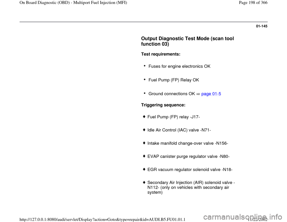
Output Diagnostic Test Mode (scan tool
function 03)
Test requirements:
Fuses for engine electronics OK
Fuel Pump (FP) Relay OK
Ground connections OK page 01
-5
Triggering sequence:
Fuel Pump (FP) relay -J17-
Idle Air Control (IAC) valve -N71-
Intake manifold change-over valve -N156-
EVAP canister purge regulator valve -N80-
EGR vacuum regulator solenoid valve -N18-
Secondary Air Injection (AIR) solenoid valve -
N112- (only on vehicles with secondary air
system)
Pa
ge 198 of 366 On Board Dia
gnostic
(OBD
) - Multi
port Fuel In
jection
(MFI
)
11/22/2002 htt
p://127.0.0.1:8080/audi/servlet/Dis
play?action=Goto&t
yp
e=re
pair&id=AUDI.B5.FU01.01.1
Page 199 of 366

Secondary Air Injection (AIR) pump relay -J299-
(only on vehicles with secondary air system)
Pa
ge 199 of 366 On Board Dia
gnostic
(OBD
) - Multi
port Fuel In
jection
(MFI
)
11/22/2002 htt
p://127.0.0.1:8080/audi/servlet/Dis
play?action=Goto&t
yp
e=re
pair&id=AUDI.B5.FU01.01.1
Page 202 of 366

01-147
Rapid data transfer
Q
03 - Output Diagnostic Test Mode
Indicated on display
- Press -Q- button to confirm input.
Output diagnostic test mode Fuel Pump
(FP) Rela
y -J17
Indicated on display
The fuel pump relay must be triggers and the fuel pump must run; the
flowing noise at the fuel pressure regulator can be clearly heard.
- If fuel pump relay is not triggered, check control page 24
-24
.
-
Press button.
Output diagnostic test mode Idle Air Control
(IAC
) valve -N71
Indicated on display
This valve is triggered (clicks) until moving on to the next output by
pressing the button. - If the valve is not triggered (does not click), check -N71- page 24
-
37
.
-
Press button.
Output diagnostic test mode Intake manifold chan
ge-over valve -N156
Indicated on display
This valve is triggered (clicks) until you move on to the next output by
pressing the button. - If the valve is not triggered (does not click), check intake manifold
change-over valve -N156- page 24
-64
.
-
Press button.
Pa
ge 202 of 366 On Board Dia
gnostic
(OBD
) - Multi
port Fuel In
jection
(MFI
)
11/22/2002 htt
p://127.0.0.1:8080/audi/servlet/Dis
play?action=Goto&t
yp
e=re
pair&id=AUDI.B5.FU01.01.1
Page 204 of 366
01-149
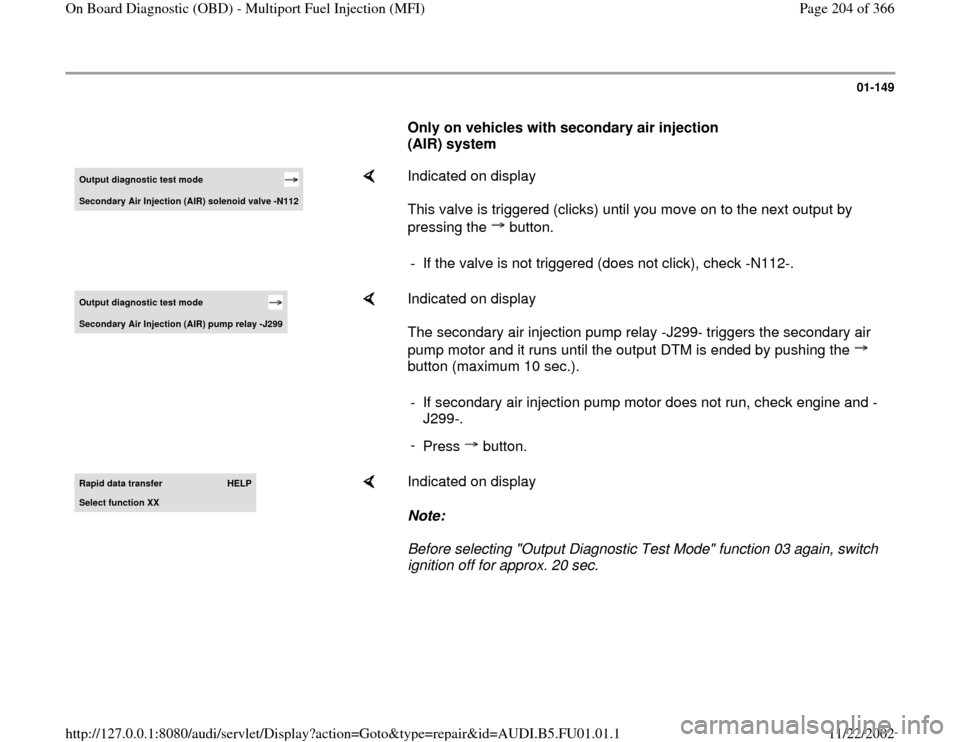
Only on vehicles with secondary air injection
(AIR) system Output diagnostic test mode Secondar
y Air In
jection
(AIR
) solenoid valve -N112
Indicated on display
This valve is triggered (clicks) until you move on to the next output by
pressing the button. - If the valve is not triggered (does not click), check -N112-.
Output diagnostic test mode Secondar
y Air In
jection
(AIR
) pump rela
y -J299
Indicated on display
The secondary air injection pump relay -J299- triggers the secondary air
pump motor and it runs until the output DTM is ended by pushing the
button (maximum 10 sec.). - If secondary air injection pump motor does not run, check engine and -
J299-.
-
Press button.
Rapid data transfer
HELP
Select function XX
Indicated on display
Note:
Before selecting "Output Diagnostic Test Mode" function 03 again, switch
ignition off for approx. 20 sec.
Pa
ge 204 of 366 On Board Dia
gnostic
(OBD
) - Multi
port Fuel In
jection
(MFI
)
11/22/2002 htt
p://127.0.0.1:8080/audi/servlet/Dis
play?action=Goto&t
yp
e=re
pair&id=AUDI.B5.FU01.01.1
Page 225 of 366
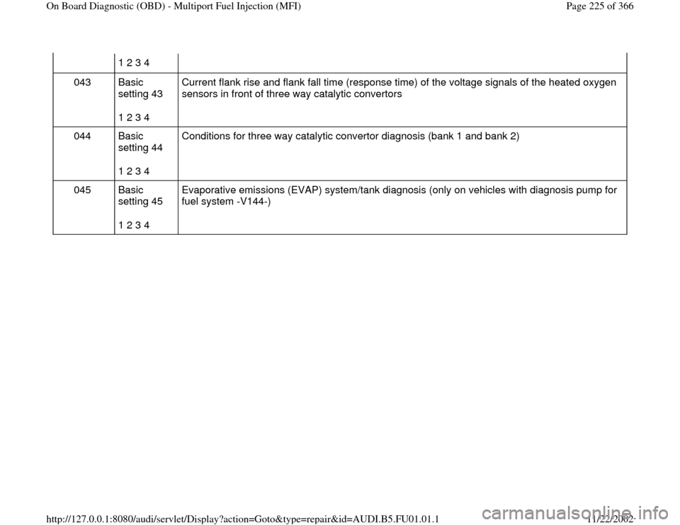
1 2 3 4
043 Basic
setting 43
1 2 3 4 Current flank rise and flank fall time (response time) of the voltage signals of the heated oxygen
sensors in front of three way catalytic convertors
044 Basic
setting 44
1 2 3 4 Conditions for three way catalytic convertor diagnosis (bank 1 and bank 2)
045 Basic
setting 45
1 2 3 4 Evaporative emissions (EVAP) system/tank diagnosis (only on vehicles with diagnosis pump for
fuel system -V144-)
Pa
ge 225 of 366 On Board Dia
gnostic
(OBD
) - Multi
port Fuel In
jection
(MFI
)
11/22/2002 htt
p://127.0.0.1:8080/audi/servlet/Dis
play?action=Goto&t
yp
e=re
pair&id=AUDI.B5.FU01.01.1
Page 245 of 366
01-175
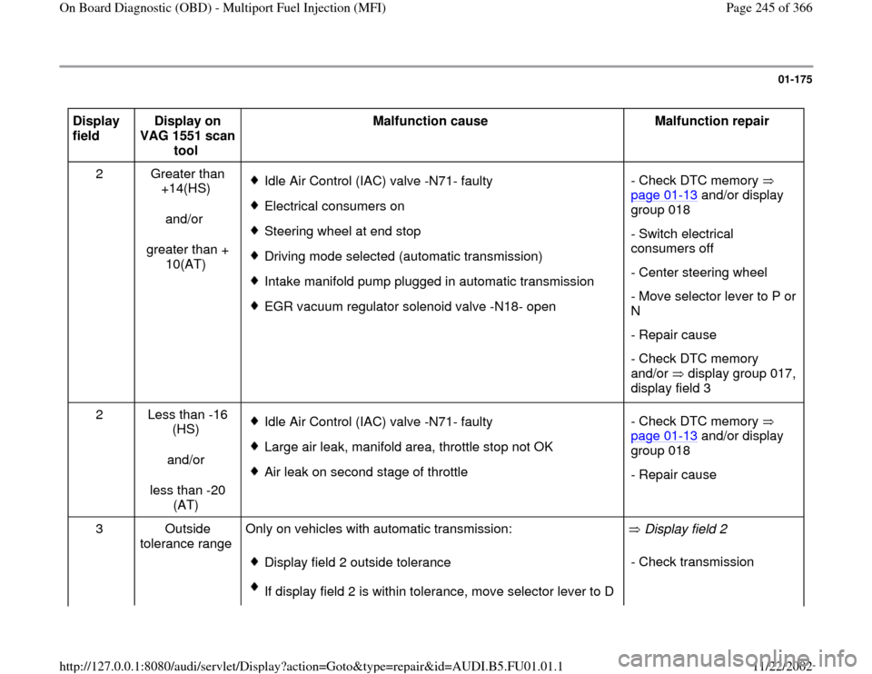
Display
field Display on
VAG 1551 scan
tool Malfunction cause
Malfunction repair
2 Greater than
+14(HS)
and/or
greater than +
10(AT)
Idle Air Control (IAC) valve -N71- faulty
Electrical consumers on
Steering wheel at end stop
Driving mode selected (automatic transmission)
Intake manifold pump plugged in automatic transmission
EGR vacuum regulator solenoid valve -N18- open- Check DTC memory
page 01
-13
and/or display
group 018
- Switch electrical
consumers off
- Center steering wheel
- Move selector lever to P or
N
- Repair cause
- Check DTC memory
and/or display group 017,
display field 3
2 Less than -16
(HS)
and/or
less than -20
(AT)
Idle Air Control (IAC) valve -N71- faulty
Large air leak, manifold area, throttle stop not OK
Air leak on second stage of throttle - Check DTC memory
page 01
-13
and/or display
group 018
- Repair cause
3 Outside
tolerance range Only on vehicles with automatic transmission:
Display field 2 outside tolerance
If display field 2 is within tolerance, move selector lever to D Display field 2
- Check transmission
Pa
ge 245 of 366 On Board Dia
gnostic
(OBD
) - Multi
port Fuel In
jection
(MFI
)
11/22/2002 htt
p://127.0.0.1:8080/audi/servlet/Dis
play?action=Goto&t
yp
e=re
pair&id=AUDI.B5.FU01.01.1
Page 325 of 366
01-231
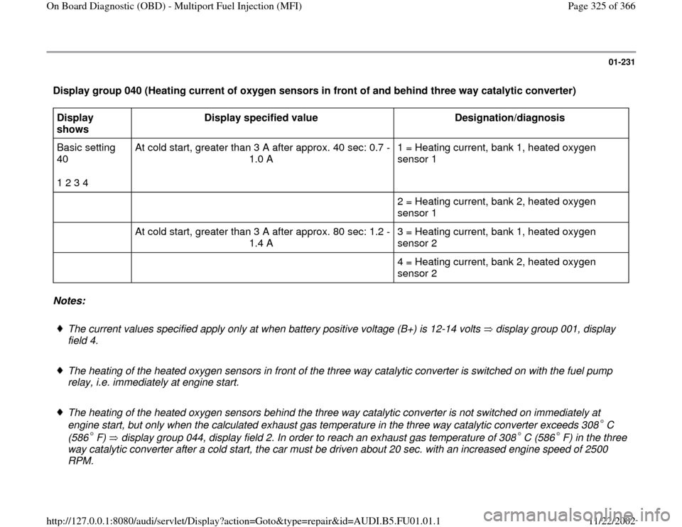
Display group 040 (Heating current of oxygen sensors in front of and behind three way catalytic converter) Display
shows Display specified value
Designation/diagnosis
Basic setting
40
1 2 3 4 At cold start, greater than 3 A after approx. 40 sec: 0.7 -
1.0 A 1 = Heating current, bank 1, heated oxygen
sensor 1
2 = Heating current, bank 2, heated oxygen
sensor 1
At cold start, greater than 3 A after approx. 80 sec: 1.2 -
1.4 A 3 = Heating current, bank 1, heated oxygen
sensor 2
4 = Heating current, bank 2, heated oxygen
sensor 2 Notes:
The current values specified apply only at when battery positive voltage (B+) is 12-14 volts display group 001, display
field 4. The heating of the heated oxygen sensors in front of the three way catalytic converter is switched on with the fuel pump
relay, i.e. immediately at engine start.
The heating of the heated oxygen sensors behind the three way catalytic converter is not switched on immediately at
engine start, but only when the calculated exhaust gas temperature in the three way catalytic converter exceeds 308 C
(586 F) display group 044, display field 2. In order to reach an exhaust gas temperature of 308 C (586 F) in the three
way catalytic converter after a cold start, the car must be driven about 20 sec. with an increased engine speed of 2500
RPM.
Pa
ge 325 of 366 On Board Dia
gnostic
(OBD
) - Multi
port Fuel In
jection
(MFI
)
11/22/2002 htt
p://127.0.0.1:8080/audi/servlet/Dis
play?action=Goto&t
yp
e=re
pair&id=AUDI.B5.FU01.01.1
Page 339 of 366
01-243
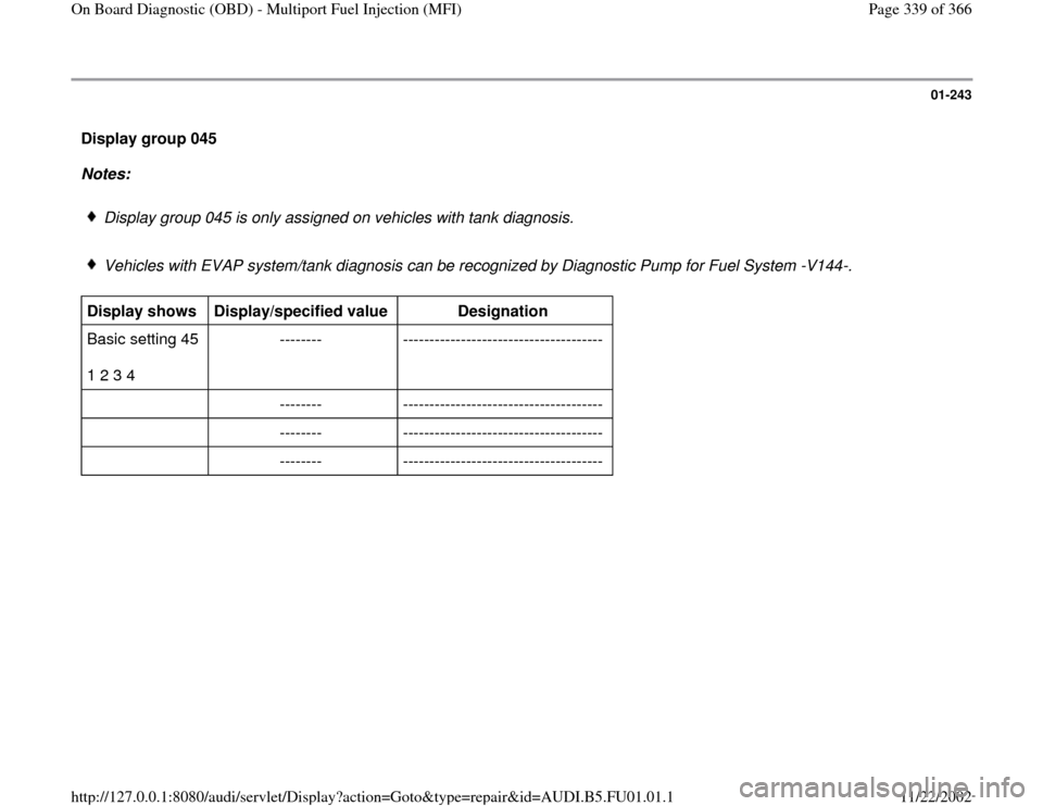
Display group 045
Notes:
Display group 045 is only assigned on vehicles with tank diagnosis.
Vehicles with EVAP system/tank diagnosis can be recognized by Diagnostic Pump for Fuel System -V144-.
Display shows
Display/specified value
Designation
Basic setting 45
1 2 3 4 -------- --------------------------------------
-------- --------------------------------------
-------- --------------------------------------
-------- --------------------------------------
Pa
ge 339 of 366 On Board Dia
gnostic
(OBD
) - Multi
port Fuel In
jection
(MFI
)
11/22/2002 htt
p://127.0.0.1:8080/audi/servlet/Dis
play?action=Goto&t
yp
e=re
pair&id=AUDI.B5.FU01.01.1