check engine AUDI A4 1999 B5 / 1.G AHA Engine On Board Diagnostic Owner's Manual
[x] Cancel search | Manufacturer: AUDI, Model Year: 1999, Model line: A4, Model: AUDI A4 1999 B5 / 1.GPages: 97, PDF Size: 0.31 MB
Page 66 of 97
01-49
Erase DTC Memory (scan tool function
05)
Required special tools and test equipment
VAG1551 Scan Tool (ST) with VAG1551/3
adapter cable
Test condition
Malfunction(s) repaired
Note:
If DTC memory has been erased, generate new
readiness code page 01
-73
.
Erasing
- Connect VAG1551/VAG1552 Scan Tool (ST)
and press buttons -0- and -1- to insert "Engine
Electronics" address word 01 (engine running at
idle) page 01
-8 .
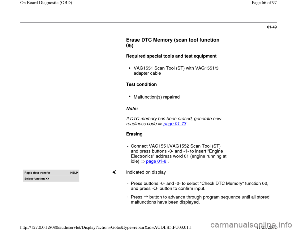
Rapid data transfer
HELP
Select function XX
Indicated on display
- Press buttons -0- and -2- to select "Check DTC Memory" function 02,
and press -Q- button to confirm input.
-
Press button to advance through program sequence until all stored
malfunctions have been displayed.
Pa
ge 66 of 97 On Board Dia
gnostic
(OBD
)
11/23/2002 htt
p://127.0.0.1:8080/audi/servlet/Dis
play?action=Goto&t
yp
e=re
pair&id=AUDI.B5.FU03.01.1
Page 69 of 97
01-51
Output Diagnostic Test Mode (DTM)
(scan tool function 03)
Notes:
The output Diagnostic Test Mode (DTM) can be
activated only with ignition switched on and the
engine not running.
The output DTM is interrupted if the engine is
started, or if a rotary pulse from the ignition
system is recognized.
When operating in the output DTM, the
individual output signals are actuated until the
program sequence is advanced by pressing the
button.
Output signals are checked by listening for the
sound of the component being actuated, or
feeling for mechanical evidence of actuation,
such as clicking, vibration, etc.
Without letting the engine run, briefly switch the
ignition off for approx. 20 seconds before
repeating the output checks.
During the entire output DTM sequence, the
electric fuel pump will run.
Pa
ge 69 of 97 On Board Dia
gnostic
(OBD
)
11/23/2002 htt
p://127.0.0.1:8080/audi/servlet/Dis
play?action=Goto&t
yp
e=re
pair&id=AUDI.B5.FU03.01.1
Page 73 of 97
01-53
Test sequence
- Connect VAG1551/VAG1552 scan tool and
insert "Engine Electronics" address word 01
(ignition on) page 01
-8 .
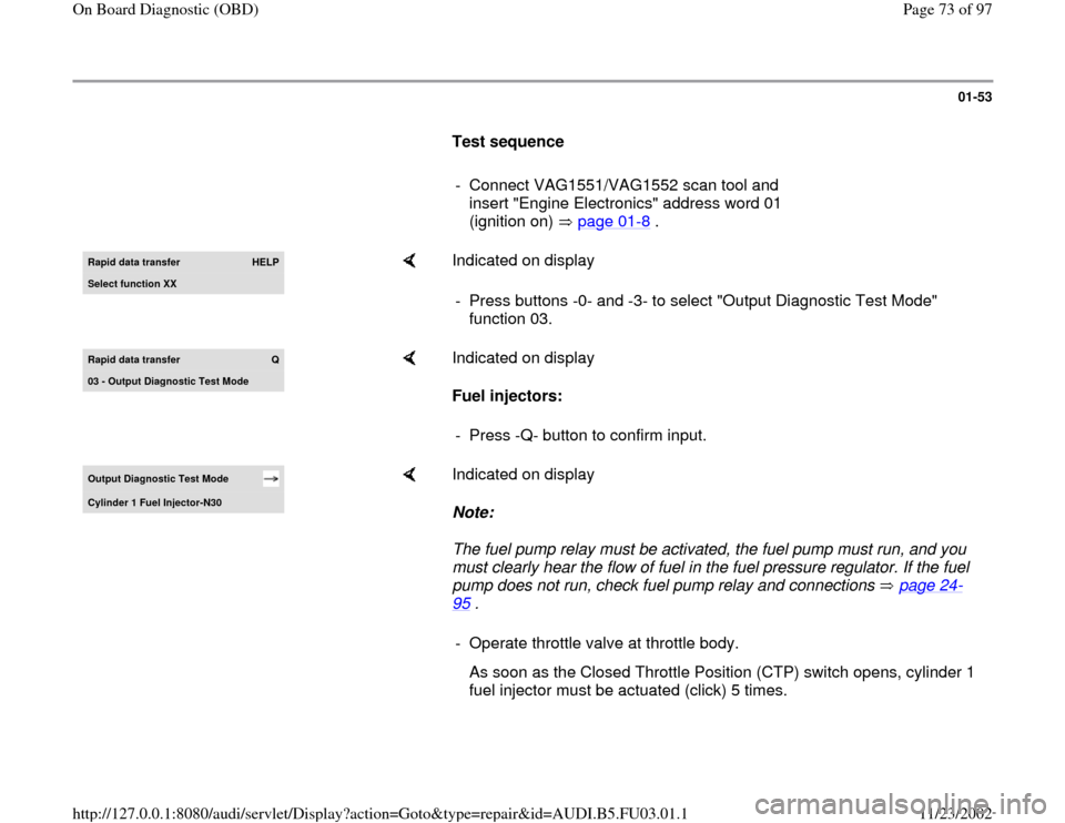
Rapid data transfer
HELP
Select function XX
Indicated on display
- Press buttons -0- and -3- to select "Output Diagnostic Test Mode"
function 03.
Rapid data transfer
Q
03 - Output Dia
gnostic Test Mode
Indicated on display
Fuel injectors:
- Press -Q- button to confirm input.
Output Diagnostic Test Mode Cylinder 1 Fuel In
jector-N30
Indicated on display
Note:
The fuel pump relay must be activated, the fuel pump must run, and you
must clearly hear the flow of fuel in the fuel pressure regulator. If the fuel
pump does not run, check fuel pump relay and connections page 24
-
95
.
- Operate throttle valve at throttle body.
As soon as the Closed Throttle Position (CTP) switch opens, cylinder 1
fuel injector must be actuated (click) 5 times.
Pa
ge 73 of 97 On Board Dia
gnostic
(OBD
)
11/23/2002 htt
p://127.0.0.1:8080/audi/servlet/Dis
play?action=Goto&t
yp
e=re
pair&id=AUDI.B5.FU03.01.1
Page 75 of 97
01-55
EVAP canister purge regulator valve -N80-:
-
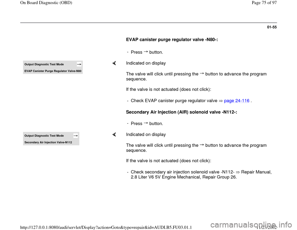
Press button.Output Diagnostic Test Mode EVAP Canister Pur
ge Re
gulator Valve-N80
Indicated on display
The valve will click until pressing the button to advance the program
sequence.
If the valve is not actuated (does not click):
Secondary Air Injection (AIR) solenoid valve -N112-: - Check EVAP canister purge regulator valve page 24
-116
.
-
Press button.
Output Diagnostic Test Mode Secondar
y Air In
jection Valve-N112
Indicated on display
The valve will click until pressing the button to advance the program
sequence.
If the valve is not actuated (does not click): - Check secondary air injection solenoid valve -N112- Repair Manual,
2.8 Liter V6 5V Engine Mechanical, Repair Group 26.
Pa
ge 75 of 97 On Board Dia
gnostic
(OBD
)
11/23/2002 htt
p://127.0.0.1:8080/audi/servlet/Dis
play?action=Goto&t
yp
e=re
pair&id=AUDI.B5.FU03.01.1
Page 76 of 97
01-56
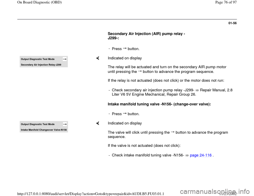
Secondary Air Injection (AIR) pump relay -
J299-:
-
Press button.Output Diagnostic Test Mode Secondary Air Injection Relay-J299
Indicated on display
The relay will be actuated and turn on the secondary AIR pump motor
until pressing the button to advance the program sequence.
If the relay is not actuated (does not click) or the motor does not run:
Intake manifold tuning valve -N156- (change-over valve): - Check secondary air injection pump relay -J299- Repair Manual, 2.8
Liter V6 5V Engine Mechanical, Repair Group 26. -
Press button.
Output Diagnostic Test Mode Intake Manifold Changeover Valve-N156
Indicated on display
The valve will click until pressing the button to advance the program
sequence.
If the valve is not actuated (does not click): - Check intake manifold tuning valve -N156- page 24
-116
.
Pa
ge 76 of 97 On Board Dia
gnostic
(OBD
)
11/23/2002 htt
p://127.0.0.1:8080/audi/servlet/Dis
play?action=Goto&t
yp
e=re
pair&id=AUDI.B5.FU03.01.1
Page 87 of 97
01-63
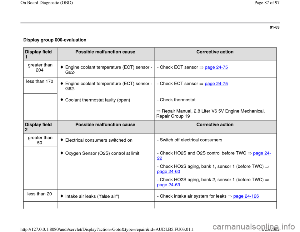
Display group 000-evaluation Display field
1
Possible malfunction cause
Corrective action
greater than
204
Engine coolant temperature (ECT) sensor -
G62- - Check ECT sensor page 24
-75
less than 170
Engine coolant temperature (ECT) sensor -
G62- - Check ECT sensor page 24
-75
Coolant thermostat faulty (open)
Repair Manual, 2.8 Liter V6 5V Engine Mechanical,
Repair Group 19 - Check thermostat
Display field
2
Possible malfunction cause
Corrective action
greater than
50
Electrical consumers switched on- Switch off electrical consumers
Oxygen Sensor (O2S) control at limit- Check HO2S and O2S control before TWC page 24
-
22
- Check HO2S aging, bank 1, sensor 1 (before TWC)
page 24
-60
- Check HO2S aging, bank 2, sensor 1 (before TWC)
page 24
-63
less than 20
Intake air leaks ("false air")- Check intake air system for leaks page 24
-126Pa
ge 87 of 97 On Board Dia
gnostic
(OBD
)
11/23/2002 htt
p://127.0.0.1:8080/audi/servlet/Dis
play?action=Goto&t
yp
e=re
pair&id=AUDI.B5.FU03.01.1
Page 89 of 97
01-64
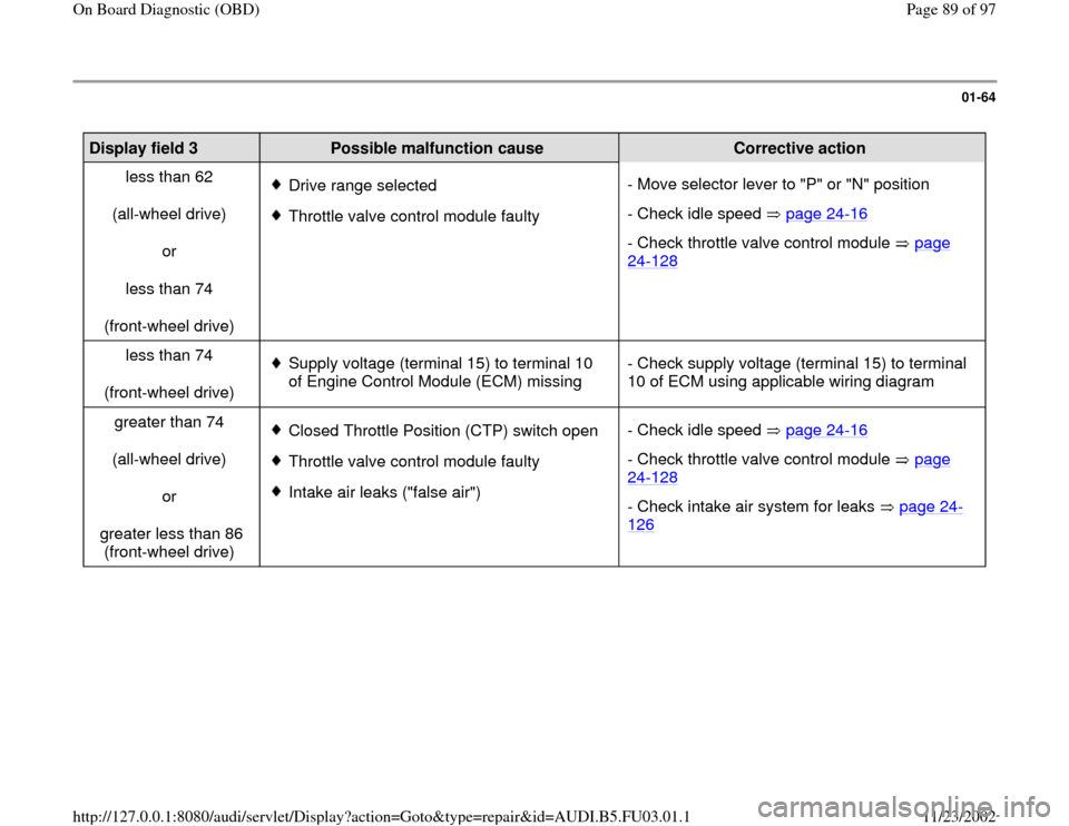
Display field 3
Possible malfunction cause
Corrective action
less than 62
(all-wheel drive)
or
less than 74
(front-wheel drive)
Drive range selected
Throttle valve control module faulty- Move selector lever to "P" or "N" position
- Check idle speed page 24
-16
- Check throttle valve control module page 24
-128
less than 74
(front-wheel drive)
Supply voltage (terminal 15) to terminal 10
of Engine Control Module (ECM) missing - Check supply voltage (terminal 15) to terminal
10 of ECM using applicable wiring diagram
greater than 74
(all-wheel drive)
or
greater less than 86
(front-wheel drive) Closed Throttle Position (CTP) switch open
Throttle valve control module faulty
Intake air leaks ("false air")- Check idle speed page 24
-16
- Check throttle valve control module page 24
-128
- Check intake air system for leaks page 24
-
126
Pa
ge 89 of 97 On Board Dia
gnostic
(OBD
)
11/23/2002 htt
p://127.0.0.1:8080/audi/servlet/Dis
play?action=Goto&t
yp
e=re
pair&id=AUDI.B5.FU03.01.1
Page 90 of 97
01-65
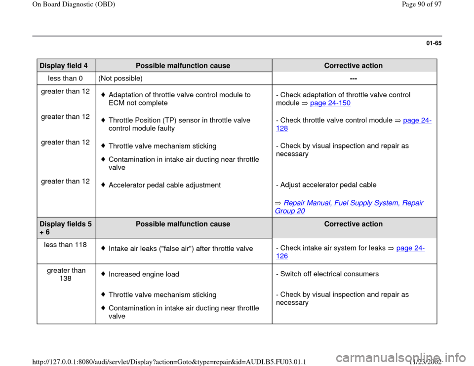
Display field 4
Possible malfunction cause
Corrective action
less than 0 (Not possible) ---
greater than 12
Adaptation of throttle valve control module to
ECM not complete - Check adaptation of throttle valve control
module page 24
-150
greater than 12
Throttle Position (TP) sensor in throttle valve
control module faulty - Check throttle valve control module page 24
-
128
greater than 12
Throttle valve mechanism sticking
Contamination in intake air ducting near throttle
valve - Check by visual inspection and repair as
necessary
greater than 12
Accelerator pedal cable adjustment
Repair Manual, Fuel Supply System, Repair
Group 20
- Adjust accelerator pedal cable
Display fields 5
+ 6
Possible malfunction cause
Corrective action
less than 118
Intake air leaks ("false air") after throttle valve- Check intake air system for leaks page 24
-
126
greater than
138
Increased engine load- Switch off electrical consumers
Throttle valve mechanism sticking
Contamination in intake air ducting near throttle
valve - Check by visual inspection and repair as
necessary
Pa
ge 90 of 97 On Board Dia
gnostic
(OBD
)
11/23/2002 htt
p://127.0.0.1:8080/audi/servlet/Dis
play?action=Goto&t
yp
e=re
pair&id=AUDI.B5.FU03.01.1
Page 91 of 97
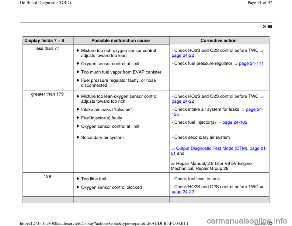
01-66
Display fields 7 + 8
Possible malfunction cause
Corrective action
less than 77
Mixture too rich-oxygen sensor control
adjusts toward too lean
Oxygen sensor control at limit
Too much fuel vapor from EVAP canister
Fuel pressure regulator faulty, or hose
disconnected - Check HO2S and O2S control before TWC
page 24
-22
- Check fuel pressure regulator page 24
-111
greater than 179
Mixture too lean-oxygen sensor control
adjusts toward too rich
Intake air leaks ("false air")
Fuel injector(s) faulty
Oxygen sensor control at limit- Check HO2S and O2S control before TWC
page 24
-22
- Check intake air system for leaks page 24
-
126
- Check fuel injector(s) page 24
-102
Secondary air system
Output Diagnostic Test Mode (DTM), page 01
-
51
and
Repair Manual, 2.8 Liter V6 5V Engine
Mechanical, Repair Group 26 - Check secondary air system
128
Too little fuel
Oxygen sensor control blocked- Check fuel level in tank
- Check HO2S and O2S control before TWC
page 24
-22
Pa
ge 91 of 97 On Board Dia
gnostic
(OBD
)
11/23/2002 htt
p://127.0.0.1:8080/audi/servlet/Dis
play?action=Goto&t
yp
e=re
pair&id=AUDI.B5.FU03.01.1