lock AUDI A4 1999 B5 / 1.G APB Engine Ignition System Checking
[x] Cancel search | Manufacturer: AUDI, Model Year: 1999, Model line: A4, Model: AUDI A4 1999 B5 / 1.GPages: 64, PDF Size: 0.37 MB
Page 1 of 64
28-1
Ignition system, checking
General notes on ignition system
Always switch off the ignition before connecting
or disconnecting the battery, otherwise the
engine control module may be damaged.
The engine control module is equipped with On
Board Diagnostic (OBD).
For trouble-free operation of the electrical
components a voltage of at least 11.5 V is
necessary.
During some of the tests it is possible that the
control module will detect and record a
malfunction. The DTC memory must therefore
be checked and if necessary erased when all
tests and repair work have been completed.
After completing troubleshooting, repairs or
component tests, it is possible that the engine
will start, run for a short period and then cut out.
If this happens it may be that the immobilizer is
blocking the engine control module. In such
cases the DTC memory must be checked and if
necessary the control module must be adapted.
Pa
ge 1 of 64 I
gnition s
ystem, checkin
g
11/22/2002 htt
p://127.0.0.1:8080/audi/servlet/Dis
play?action=Goto&t
yp
e=re
pair&id=AUDI.B5.FU04.28.1
Page 19 of 64
28-17
Intake Air Temperature (IAT) sensor -
G42, checking
Location of sensor and connector Page 24
-5 .
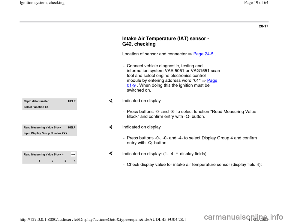
- Connect vehicle diagnostic, testing and
information system VAS 5051 or VAG1551 scan
tool and select engine electronics control
module by entering address word "01" Page
01
-9 . When doing this the ignition must be
switched on.
Rapid data transfer
HELP
Select Function XX
Indicated on display
- Press buttons -0- and -8- to select function "Read Measuring Value
Block" and confirm entry with -Q- button.
Read Measurin
g Value Block
HELP
Input Displa
y Group Number XXX
Indicated on display
- Press buttons -0-, -0- and -4- to select Display Group 4 and confirm
entry with -Q- button.
Read Measuring Value Block 4
1
2
3
4
Indicated on display: (1...4 display fields) - Check display value for intake air temperature sensor (display field 4):
Pa
ge 19 of 64 I
gnition s
ystem, checkin
g
11/22/2002 htt
p://127.0.0.1:8080/audi/servlet/Dis
play?action=Goto&t
yp
e=re
pair&id=AUDI.B5.FU04.28.1
Page 29 of 64
28-26
Rapid data transfer
HELP
Select function XX
Indicated on display
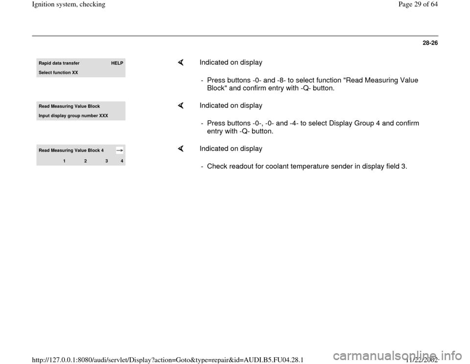
- Press buttons -0- and -8- to select function "Read Measuring Value
Block" and confirm entry with -Q- button.
Read Measuring Value Block Input displa
y group number XXX
Indicated on display
- Press buttons -0-, -0- and -4- to select Display Group 4 and confirm
entry with -Q- button.
Read Measuring Value Block 4
1
2
3
4
Indicated on display
- Check readout for coolant temperature sender in display field 3.
Pa
ge 29 of 64 I
gnition s
ystem, checkin
g
11/22/2002 htt
p://127.0.0.1:8080/audi/servlet/Dis
play?action=Goto&t
yp
e=re
pair&id=AUDI.B5.FU04.28.1
Page 38 of 64
28-34
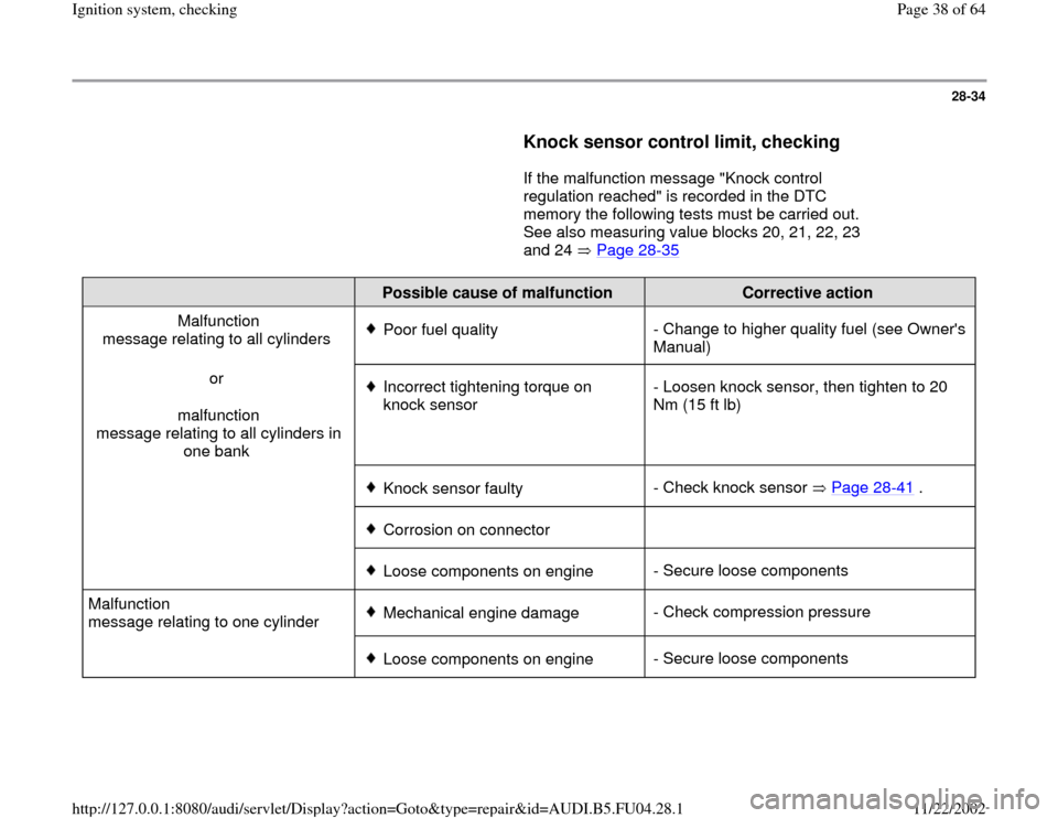
Knock sensor control limit, checking
If the malfunction message "Knock control
regulation reached" is recorded in the DTC
memory the following tests must be carried out.
See also measuring value blocks 20, 21, 22, 23
and 24 Page 28
-35
Possible cause of malfunction
Corrective action
Malfunction
message relating to all cylinders
Poor fuel quality- Change to higher quality fuel (see Owner's
Manual)
or
malfunction
message relating to all cylinders in
one bank Incorrect tightening torque on
knock sensor - Loosen knock sensor, then tighten to 20
Nm (15 ft lb)
Knock sensor faulty- Check knock sensor Page 28
-41
.
Corrosion on connector
Loose components on engine- Secure loose components
Malfunction
message relating to one cylinder Mechanical engine damage- Check compression pressure
Loose components on engine- Secure loose components
Pa
ge 38 of 64 I
gnition s
ystem, checkin
g
11/22/2002 htt
p://127.0.0.1:8080/audi/servlet/Dis
play?action=Goto&t
yp
e=re
pair&id=AUDI.B5.FU04.28.1
Page 39 of 64
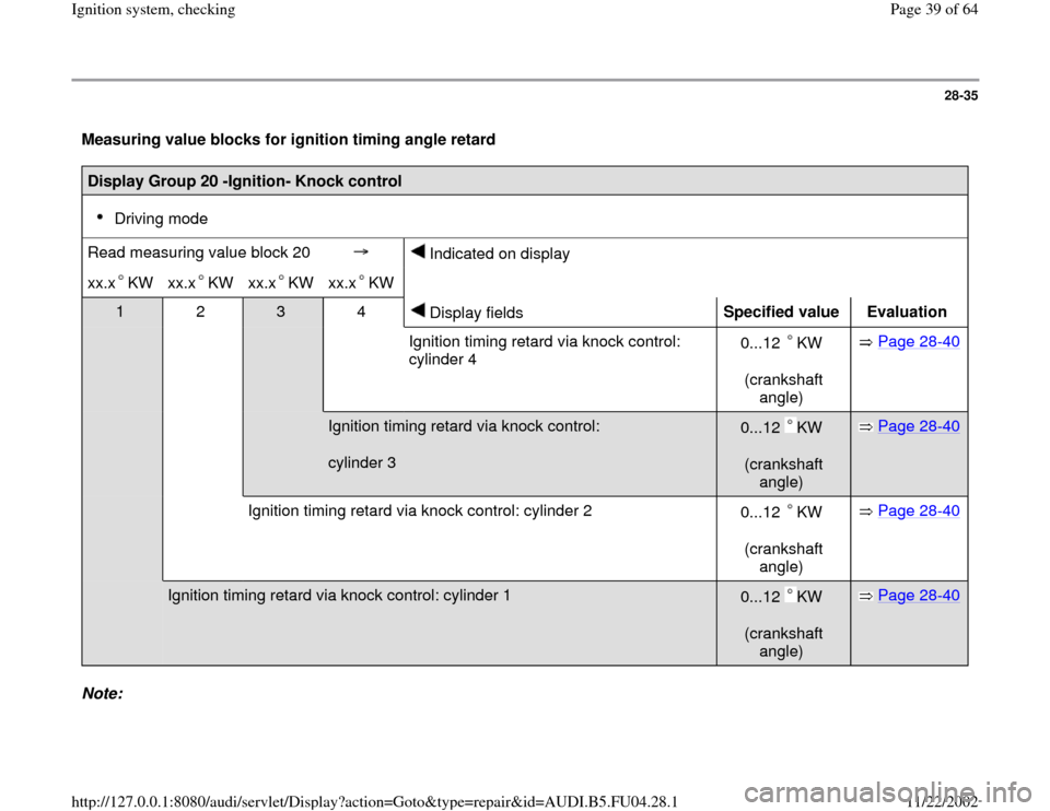
28-35
Measuring value blocks for ignition timing angle retard Display Group 20 -Ignition- Knock control
Driving mode
Read measuring value block 20
Indicated on display
xx.x KW
xx.x KW
xx.x KW
xx.x KW
1 2
3 4
Display fields
Specified value
Evaluation
Ignition timing retard via knock control:
cylinder 4 0...12 KW
(crankshaft
angle)
Page 28
-40
Ignition timing retard via knock control:
cylinder 3
0...12 KW
(crankshaft
angle)
Page 28
-40
Ignition timing retard via knock control: cylinder 2
0...12 KW
(crankshaft
angle)
Page 28
-40
Ignition timing retard via knock control: cylinder 1
0...12 KW
(crankshaft
angle)
Page 28
-40
Note:
Pa
ge 39 of 64 I
gnition s
ystem, checkin
g
11/22/2002 htt
p://127.0.0.1:8080/audi/servlet/Dis
play?action=Goto&t
yp
e=re
pair&id=AUDI.B5.FU04.28.1
Page 41 of 64

28-36
Display Group 21 -Ignition- Knock control
Driving mode
Read measuring value block 21
Indicated on display
xx.x KW
xx.x KW
1 2
3 4
Display fields
Specified value
Evaluation
Ignition timing retard via knock control: cylinder 6
0...12 KW
(crankshaft angle)
Page 28
-40
Ignition timing retard via knock control: cylinder 5
0...12 KW
(crankshaft angle)
Page 28
-40
Note:
The displayed digit values in display fields 1 and 2 reflects the actual "ignition timing retard" via knock control from the
individual cylinders. The ignition timing retard occurs via KW (crankshaft angle).
Pa
ge 41 of 64 I
gnition s
ystem, checkin
g
11/22/2002 htt
p://127.0.0.1:8080/audi/servlet/Dis
play?action=Goto&t
yp
e=re
pair&id=AUDI.B5.FU04.28.1
Page 42 of 64

28-37
Display Group 22 -Ignition- Knock control
Driving mode
Read measuring value block
22
Indicated on display
xx.x RPM x.x %
xx.x KW
xx.x KW
1 2
3 4
Display fields
Specified value
Evaluation
Ignition timing retard via knock control:
cylinder 2 0...12 KW
(crankshaft
angle)
Page 28
-40
Ignition timing retard via knock control:
cylinder 1
0...12 KW
(crankshaft
angle)
Page 28
-40
Engine load 15 - 175 %
Engine speed RPM
750 - 6800 RPM
Note:
The displayed digit values in display fields 3 and 4 reflects the actual "ignition timing retard" via knock control from cylinders 1
and 2. The ignition timing retard occurs via KW (crankshaft angle).
Pa
ge 42 of 64 I
gnition s
ystem, checkin
g
11/22/2002 htt
p://127.0.0.1:8080/audi/servlet/Dis
play?action=Goto&t
yp
e=re
pair&id=AUDI.B5.FU04.28.1
Page 43 of 64

28-38
Display Group 23 -Ignition- Knock control
Driving mode
Read measuring value block
23
Indicated on display
xx.x RPM x.x %
xx.x KW
xx.x KW
1 2
3 4
Display fields
Specified value
Evaluation
Ignition timing retard via knock control:
cylinder 4 0...12 KW
(crankshaft
angle)
Page 28
-40
Ignition timing retard via knock control:
cylinder 3
0...12 KW
(crankshaft
angle)
Page 28
-40
Engine load 15 - 175 %
Engine speed RPM
750 - 6800 RPM
Note:
The displayed digit values in display fields 3 and 4 reflects the actual "ignition timing retard" via knock control from cylinders 3
and 4. The ignition timing retard occurs via KW (crankshaft angle).
Pa
ge 43 of 64 I
gnition s
ystem, checkin
g
11/22/2002 htt
p://127.0.0.1:8080/audi/servlet/Dis
play?action=Goto&t
yp
e=re
pair&id=AUDI.B5.FU04.28.1
Page 44 of 64

28-39
Display Group 24 -Ignition- Knock control
Driving mode
Read measuring value block
24
Indicated on display
xx.x RPM x.x %
xx.x KW
xx.x KW
1 2
3 4
Display fields
Specified value
Evaluation
Ignition timing retard via knock control:
cylinder 6 0...12 KW
(crankshaft
angle)
Page 28
-40
Ignition timing retard via knock control:
cylinder 5
0...12 KW
(crankshaft
angle)
Page 28
-40
Engine load 15 - 175 %
Engine speed RPM
750 - 6800 RPM
Note:
The displayed digit values in display fields 3 and 4 reflects the actual "ignition timing retard" via knock control from cylinders 5
and 6. The ignition timing retard occurs via KW (crankshaft angle).
Pa
ge 44 of 64 I
gnition s
ystem, checkin
g
11/22/2002 htt
p://127.0.0.1:8080/audi/servlet/Dis
play?action=Goto&t
yp
e=re
pair&id=AUDI.B5.FU04.28.1
Page 57 of 64
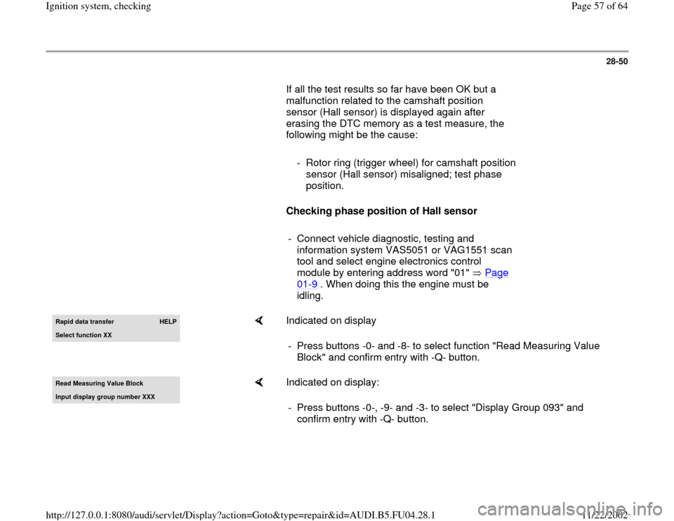
28-50
If all the test results so far have been OK but a
malfunction related to the camshaft position
sensor (Hall sensor) is displayed again after
erasing the DTC memory as a test measure, the
following might be the cause:
- Rotor ring (trigger wheel) for camshaft position
sensor (Hall sensor) misaligned; test phase
position.
Checking phase position of Hall sensor
- Connect vehicle diagnostic, testing and
information system VAS5051 or VAG1551 scan
tool and select engine electronics control
module by entering address word "01" Page
01
-9 . When doing this the engine must be
idling.
Rapid data transfer
HELP
Select function XX
Indicated on display
- Press buttons -0- and -8- to select function "Read Measuring Value
Block" and confirm entry with -Q- button.
Read Measurin
g Value Block
Input displa
y group number XXX
Indicated on display:
- Press buttons -0-, -9- and -3- to select "Display Group 093" and
confirm entry with -Q- button.
Pa
ge 57 of 64 I
gnition s
ystem, checkin
g
11/22/2002 htt
p://127.0.0.1:8080/audi/servlet/Dis
play?action=Goto&t
yp
e=re
pair&id=AUDI.B5.FU04.28.1