ignition AUDI A4 1999 B5 / 1.G APB Engine Motronic Multiport Fuel Injection System Servising Workshop Manual
[x] Cancel search | Manufacturer: AUDI, Model Year: 1999, Model line: A4, Model: AUDI A4 1999 B5 / 1.GPages: 90, PDF Size: 0.84 MB
Page 1 of 90
24-1
Motronic Multiport Fuel
Injection (MFI) system,
servicing
Safety precautions
Observe following precautions if test and
measuring instruments are required during a
road test:
WARNING!
During a road test in an airbag equipped
vehicle, test equipment must always be
fastened to and operated from the rear seat
by a second technician.
When driving or riding in an airbag equipped
vehicle, NEVER hold the scan tool or other
test equipment in your hands or lap while in
motion. Objects between you and and the
airbag increase the risk of injury in an
accident.
To prevent injuries to persons and/or damage
to the fuel injection and ignition system, the
following must be noted:
Always switch off the ignition before
connecting or disconnecting injection or
ignition system wiring or tester cables.
Pa
ge 1 of 90 Motronic Multi
port Fuel In
jection
(MFI
) system, servicin
g
11/22/2002 htt
p://127.0.0.1:8080/audi/servlet/Dis
play?action=Goto&t
yp
e=re
pair&id=AUDI.B5.FU04.24.1
Page 3 of 90
24-2
CAUTION!
To operate the engine at starter speed
without actually starting it (for example, in
order to test compression), unplug the
connectors from the output stages for the
ignition coils and also the connectors on the
injectors.
During some of the tests the control module
may identify and record malfunctions. The
DTC memory should therefore be checked
and (if necessary) erased after completing
the tests and any repair work that may be
required. After erasing DTC memory
generate new readiness code Page 01
-
105
.
Always switch off the ignition before
cleaning the engine.
Always switch off the ignition before
connecting or disconnecting the battery,
otherwise the engine control module may be
damaged.
Be sure of proper radio code (for vehicles
equipped with coded anti-theft radio)
Be sure the battery negative (-) cable is
Pa
ge 3 of 90 Motronic Multi
port Fuel In
jection
(MFI
) system, servicin
g
11/22/2002 htt
p://127.0.0.1:8080/audi/servlet/Dis
play?action=Goto&t
yp
e=re
pair&id=AUDI.B5.FU04.24.1
Page 4 of 90
disconnected, when:
Working on the electrical system.
When connecting and disconnecting
electrical test equipment (LED voltage tester,
multimeter, etc.):
Be sure the ignition is switched OFF.
Use correct adapters from the VAG1594
connector test kit.
Pa
ge 4 of 90 Motronic Multi
port Fuel In
jection
(MFI
) system, servicin
g
11/22/2002 htt
p://127.0.0.1:8080/audi/servlet/Dis
play?action=Goto&t
yp
e=re
pair&id=AUDI.B5.FU04.24.1
Page 12 of 90
24-10
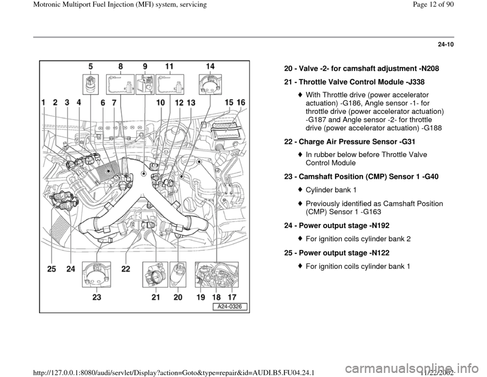
20 -
Valve -2- for camshaft adjustment -N208
21 -
Throttle Valve Control Module -J338
With Throttle drive (power accelerator
actuation) -G186, Angle sensor -1- for
throttle drive (power accelerator actuation)
-G187 and Angle sensor -2- for throttle
drive (power accelerator actuation) -G188
22 -
Charge Air Pressure Sensor -G31 In rubber below before Throttle Valve
Control Module
23 -
Camshaft Position (CMP) Sensor 1 -G40 Cylinder bank 1Previously identified as Camshaft Position
(CMP) Sensor 1 -G163
24 -
Power output stage -N192 For ignition coils cylinder bank 2
25 -
Power output stage -N122 For ignition coils cylinder bank 1
Pa
ge 12 of 90 Motronic Multi
port Fuel In
jection
(MFI
) system, servicin
g
11/22/2002 htt
p://127.0.0.1:8080/audi/servlet/Dis
play?action=Goto&t
yp
e=re
pair&id=AUDI.B5.FU04.24.1
Page 14 of 90
24-12
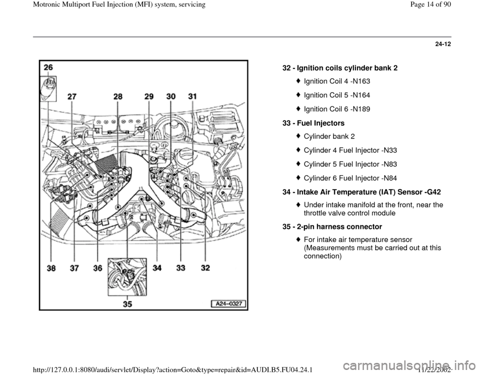
32 -
Ignition coils cylinder bank 2
Ignition Coil 4 -N163Ignition Coil 5 -N164Ignition Coil 6 -N189
33 -
Fuel Injectors Cylinder bank 2Cylinder 4 Fuel Injector -N33Cylinder 5 Fuel Injector -N83Cylinder 6 Fuel Injector -N84
34 -
Intake Air Temperature (IAT) Sensor -G42 Under intake manifold at the front, near the
throttle valve control module
35 -
2-pin harness connector For intake air temperature sensor
(Measurements must be carried out at this
connection)
Pa
ge 14 of 90 Motronic Multi
port Fuel In
jection
(MFI
) system, servicin
g
11/22/2002 htt
p://127.0.0.1:8080/audi/servlet/Dis
play?action=Goto&t
yp
e=re
pair&id=AUDI.B5.FU04.24.1
Page 15 of 90
24-13
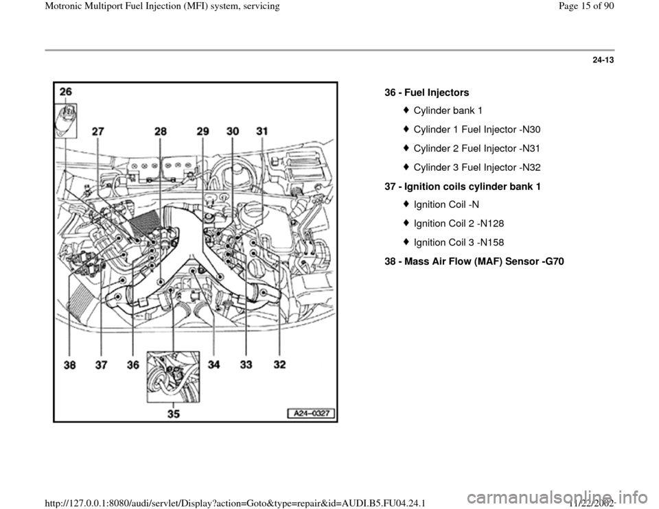
36 -
Fuel Injectors
Cylinder bank 1Cylinder 1 Fuel Injector -N30Cylinder 2 Fuel Injector -N31Cylinder 3 Fuel Injector -N32
37 -
Ignition coils cylinder bank 1 Ignition Coil -NIgnition Coil 2 -N128Ignition Coil 3 -N158
38 -
Mass Air Flow (MAF) Sensor -G70
Pa
ge 15 of 90 Motronic Multi
port Fuel In
jection
(MFI
) system, servicin
g
11/22/2002 htt
p://127.0.0.1:8080/audi/servlet/Dis
play?action=Goto&t
yp
e=re
pair&id=AUDI.B5.FU04.24.1
Page 24 of 90
24-21
Work sequence
- Switch off ignition.
- Pull rubber gasket forward.
- Remove plenum cover forward.
- Remove cover for E-box (in plenum chamber).
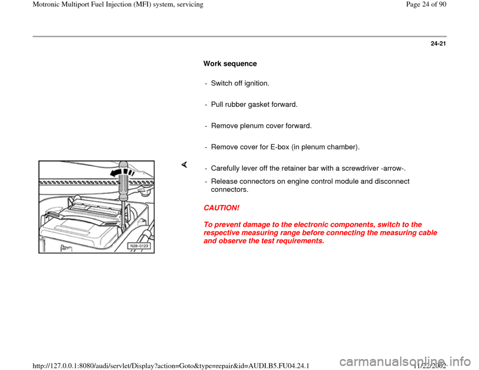
CAUTION!
To prevent damage to the electronic components, switch to the
respective measuring range before connecting the measuring cable
and observe the test requirements. - Carefully lever off the retainer bar with a screwdriver -arrow-.
- Release connectors on engine control module and disconnect
connectors.
Pa
ge 24 of 90 Motronic Multi
port Fuel In
jection
(MFI
) system, servicin
g
11/22/2002 htt
p://127.0.0.1:8080/audi/servlet/Dis
play?action=Goto&t
yp
e=re
pair&id=AUDI.B5.FU04.24.1
Page 27 of 90
24-24
Motronic Engine Control Module (ECM) -
J220, replacing
Note:
When the engine control module is disconnected
the learned values are erased but the contents of
the DTC memory remain intact.
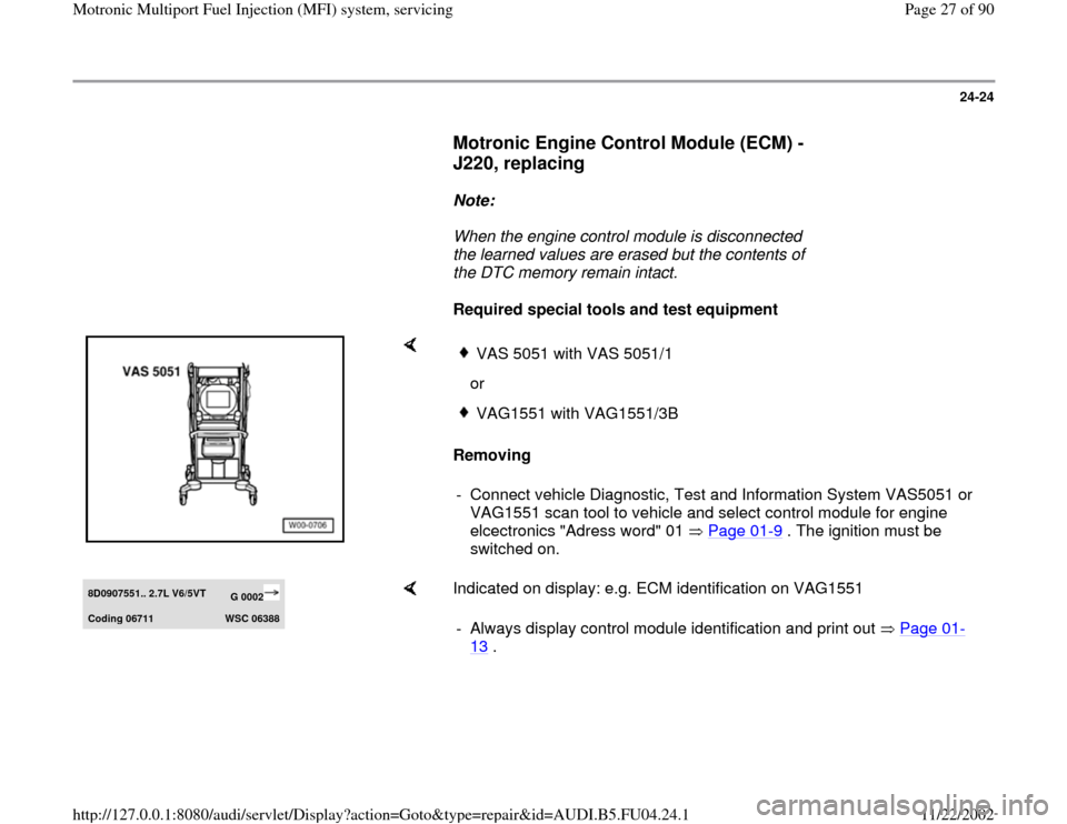
Required special tools and test equipment
Removing
VAS 5051 with VAS 5051/1
orVAG1551 with VAG1551/3B
- Connect vehicle Diagnostic, Test and Information System VAS5051 or
VAG1551 scan tool to vehicle and select control module for engine
elcectronics "Adress word" 01 Page 01
-9 . The ignition must be
switched on.
8D0907551.. 2.7L V6/5VT
G 0002
Codin
g 06711
WSC 06388
Indicated on display: e.g. ECM identification on VAG1551
- Always display control module identification and print out Page 01
-
13
.
Pa
ge 27 of 90 Motronic Multi
port Fuel In
jection
(MFI
) system, servicin
g
11/22/2002 htt
p://127.0.0.1:8080/audi/servlet/Dis
play?action=Goto&t
yp
e=re
pair&id=AUDI.B5.FU04.24.1
Page 28 of 90
24-25
- Compare coding with coding variation table
Page 01
-93
.
- Switch ignition off.
- Pull rubber gasket forward.
- Remove plenum cover forward.
- Remove cover for E-box (in plenum chamber).
Installing
Installation is performed in the reverse sequence. However note the
following:
Note:
At the first learning (adaptation) phase during the "Engine-Basic Setting"
the engine might run a little rough at idle and bucks/jerks a little while
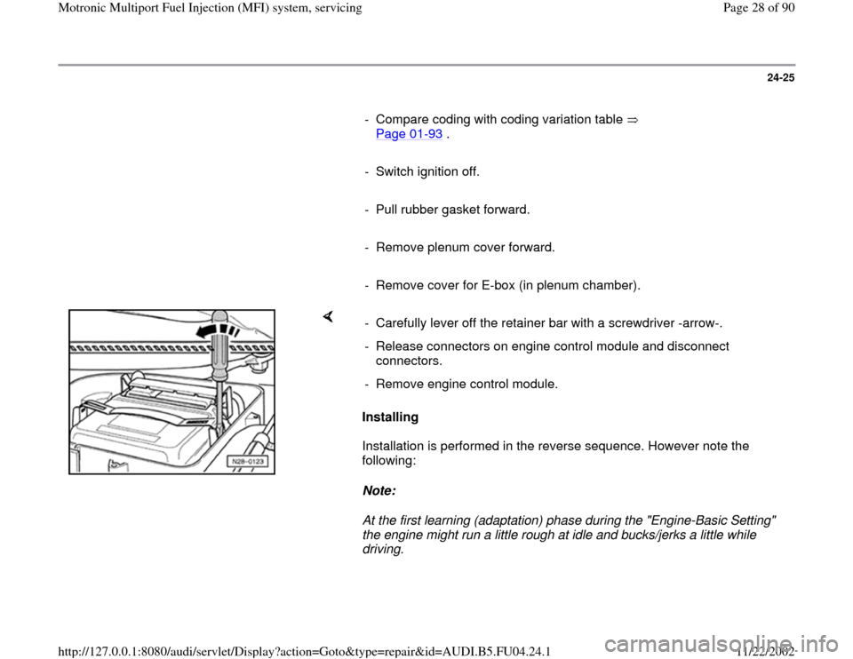
driving. - Carefully lever off the retainer bar with a screwdriver -arrow-.
- Release connectors on engine control module and disconnect
connectors.
- Remove engine control module.
Pa
ge 28 of 90 Motronic Multi
port Fuel In
jection
(MFI
) system, servicin
g
11/22/2002 htt
p://127.0.0.1:8080/audi/servlet/Dis
play?action=Goto&t
yp
e=re
pair&id=AUDI.B5.FU04.24.1
Page 43 of 90
24-37
Note:
A rise in pressure (due to fuel expansion) when
the engine is at operating temperature is normal.
- Start the engine and run at idling speed.
- Switch ignition off after the pressure has built-
up. At the same time close pressure gauge cut-
off tap (lever at 90 to through flow direction). If the pressure does not drop, the following faults
are possible:
Union between pressure gauge and fuel supply
pipe leaking
Supply pipe leaking at fuel tank
Return valve in fuel pump leaking
Repair Manual, Fuel Supply System, Repair
Group 20
Note:
When the cut-off tap is closed the pressure
gauge will indicate the pressure downstream of
Pa
ge 43 of 90 Motronic Multi
port Fuel In
jection
(MFI
) system, servicin
g
11/22/2002 htt
p://127.0.0.1:8080/audi/servlet/Dis
play?action=Goto&t
yp
e=re
pair&id=AUDI.B5.FU04.24.1