AUDI A4 1999 B5 / 1.G Brakes Basic Setting 04 Owner's Guide
Manufacturer: AUDI, Model Year: 1999, Model line: A4, Model: AUDI A4 1999 B5 / 1.GPages: 64, PDF Size: 0.31 MB
Page 31 of 64
01-270
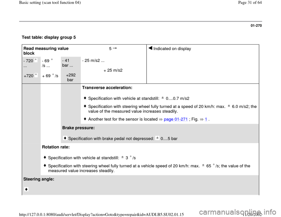
Test table: display group 5 Read measuring value
block 5
Indicated on display
- 720
...
+720
- 69
/s ...
+ 69 /s
- 41
bar ...
+292
bar - 25 m/s2 ...
+ 25 m/s2
Transverse acceleration:
Specification with vehicle at standstill: 0....0.7 m/s2 Specification with steering wheel fully turned at a speed of 20 km/h: max. 6.0 m/s2; the
value of the measured value increases steadily. Another test for the sensor is located page 01
-271
; Fig. 1
.
Brake pressure:
Specification with brake pedal not depressed: 0....5 bar
Rotation rate:
Specification with vehicle at standstill: 3 /sSpecification with steering wheel fully turned at a vehicle speed of 20 km/h: max. 65 /s; the value of the
measured value increases steadily.
Steering angle:
Pa
ge 31 of 64 Basic settin
g (scan tool function 04
)
11/20/2002 htt
p://127.0.0.1:8080/audi/servlet/Dis
play?action=Goto&t
yp
e=re
pair&id=AUDI.B5.SU02.01.15
Page 32 of 64
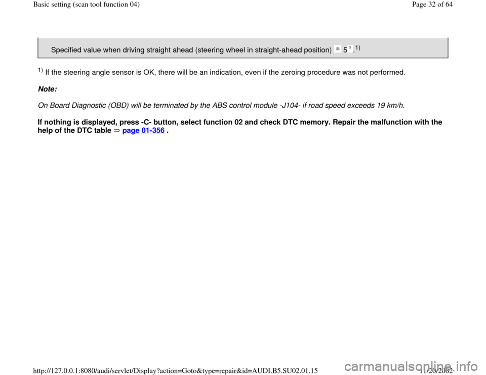
Specified value when driving straight ahead (steering wheel in straight-ahead position) 5 .
1)
1) If the steering angle sensor is OK, there will be an indication, even if the zeroing procedure was not performed.
Note:
On Board Diagnostic (OBD) will be terminated by the ABS control module -J104- if road speed exceeds 19 km/h.
If nothing is displayed, press -C- button, select function 02 and check DTC memory. Repair the malfunction with the
help of the DTC table page 01
-356
.
Pa
ge 32 of 64 Basic settin
g (scan tool function 04
)
11/20/2002 htt
p://127.0.0.1:8080/audi/servlet/Dis
play?action=Goto&t
yp
e=re
pair&id=AUDI.B5.SU02.01.15
Page 33 of 64
01-271
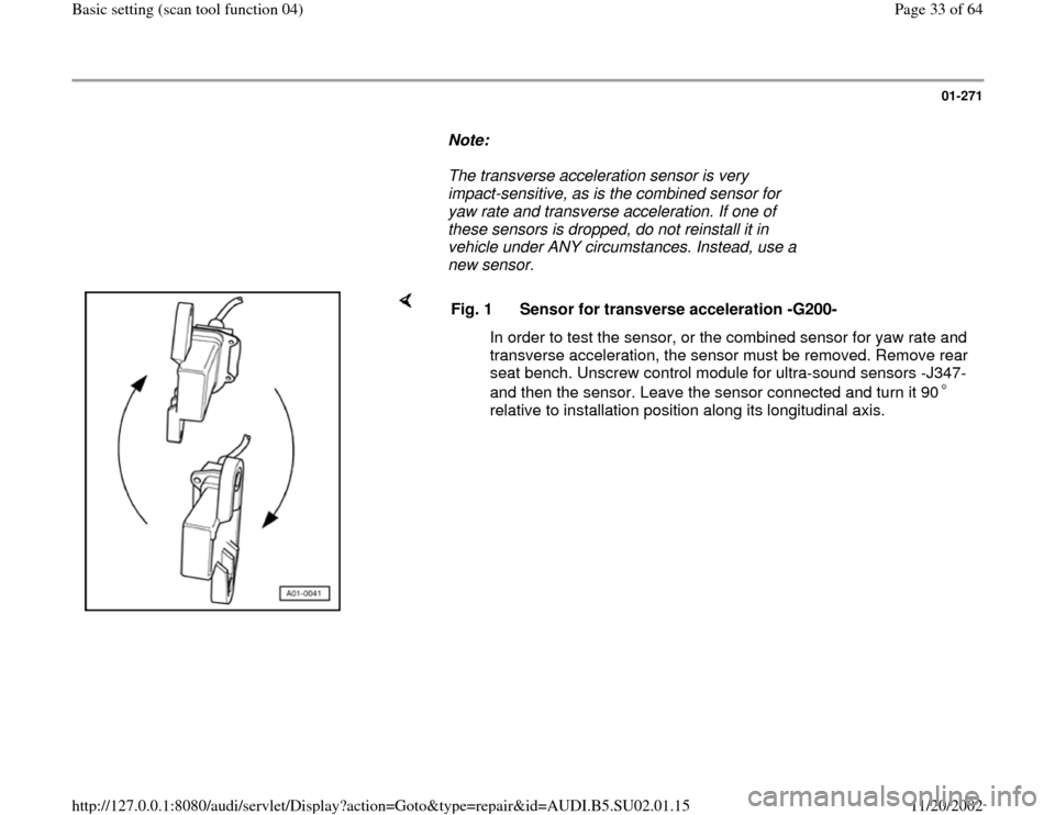
Note:
The transverse acceleration sensor is very
impact-sensitive, as is the combined sensor for
yaw rate and transverse acceleration. If one of
these sensors is dropped, do not reinstall it in
vehicle under ANY circumstances. Instead, use a
new sensor.
Fig. 1 Sensor for transverse acceleration -G200-
In order to test the sensor, or the combined sensor for yaw rate and
transverse acceleration, the sensor must be removed. Remove rear
seat bench. Unscrew control module for ultra-sound sensors -J347-
and then the sensor. Leave the sensor connected and turn it 90
relative to installation position along its longitudinal axis.
Pa
ge 33 of 64 Basic settin
g (scan tool function 04
)
11/20/2002 htt
p://127.0.0.1:8080/audi/servlet/Dis
play?action=Goto&t
yp
e=re
pair&id=AUDI.B5.SU02.01.15
Page 34 of 64
01-272
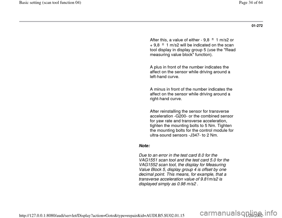
After this, a value of either - 9,8 1 m/s2 or
+ 9,8 1 m/s2 will be indicated on the scan
tool display in display group 5 (use the "Read
measuring value block" function).
A plus in front of the number indicates the
affect on the sensor while driving around a
left-hand curve.
A minus in front of the number indicates the
affect on the sensor while driving around a
right-hand curve.
After reinstalling the sensor for transverse
acceleration -G200- or the combined sensor
for yaw rate and transverse acceleration,
tighten the mounting bolts to 5 Nm. Tighten
the mounting bolts for the control module for
ultra-sound sensors -J347- to 2 Nm.
Note:
Due to an error in the test card 8.0 for the
VAG1551 scan tool and the test card 5.0 for the
VAG1552 scan tool, the display for Measuring
Value Block 5, display group 4 is offset by one
decimal point. This means, for example, that a
transverse acceleration value of 9.81m/s2 is
displayed simply as 0.98 m/s2 .
Pa
ge 34 of 64 Basic settin
g (scan tool function 04
)
11/20/2002 htt
p://127.0.0.1:8080/audi/servlet/Dis
play?action=Goto&t
yp
e=re
pair&id=AUDI.B5.SU02.01.15
Page 35 of 64

01-273
Note:
The display group numbers can be selected in
sequence by pressing buttons <-1 and 3-> on the
VAG1551 scan tool, or the arrow buttons and
on the VAG1552 mobile scan tool or the arrow
buttons and on the screen of the VAS5051
tester.
- Press -C- button to input display group number
manually. Read measurin
g value block
Enter display group number XXX
Indicated on display:
- Press buttons -0-, -0- and -6-.
- Press -Q- button to confirm input.
Pa
ge 35 of 64 Basic settin
g (scan tool function 04
)
11/20/2002 htt
p://127.0.0.1:8080/audi/servlet/Dis
play?action=Goto&t
yp
e=re
pair&id=AUDI.B5.SU02.01.15
Page 36 of 64
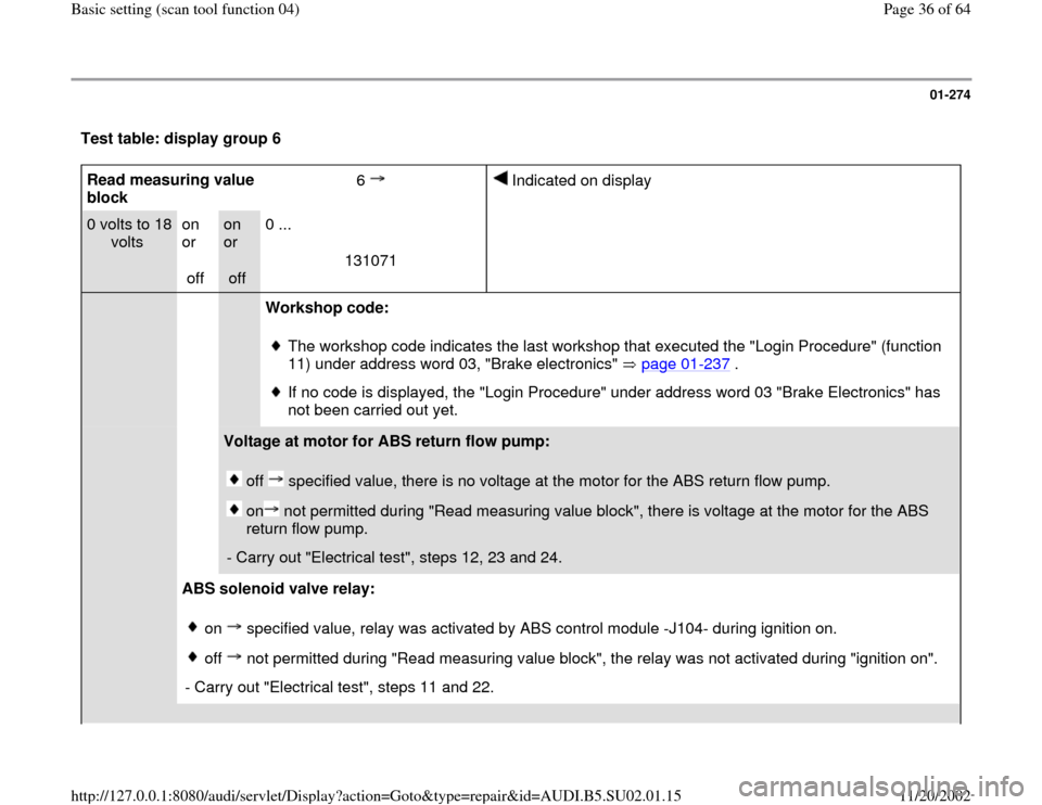
01-274
Test table: display group 6 Read measuring value
block 6
Indicated on display
0 volts to 18
volts
on
or
off
on
or
off 0 ...
131071
Workshop code:
The workshop code indicates the last workshop that executed the "Login Procedure" (function
11) under address word 03, "Brake electronics" page 01
-237
.
If no code is displayed, the "Login Procedure" under address word 03 "Brake Electronics" has
not been carried out yet.
Voltage at motor for ABS return flow pump:
off specified value, there is no voltage at the motor for the ABS return flow pump. on not permitted during "Read measuring value block", there is voltage at the motor for the ABS
return flow pump.
- Carry out "Electrical test", steps 12, 23 and 24.
ABS solenoid valve relay:
on specified value, relay was activated by ABS control module -J104- during ignition on. off not permitted during "Read measuring value block", the relay was not activated during "ignition on".
- Carry out "Electrical test", steps 11 and 22.
Pa
ge 36 of 64 Basic settin
g (scan tool function 04
)
11/20/2002 htt
p://127.0.0.1:8080/audi/servlet/Dis
play?action=Goto&t
yp
e=re
pair&id=AUDI.B5.SU02.01.15
Page 37 of 64

Supply voltage for ABS control module -J104- at terminal 1:
Specification: 10.5 - 14.5 V
- If specified value is not obtained, carry out "Electrical test", step 21.
Pa
ge 37 of 64 Basic settin
g (scan tool function 04
)
11/20/2002 htt
p://127.0.0.1:8080/audi/servlet/Dis
play?action=Goto&t
yp
e=re
pair&id=AUDI.B5.SU02.01.15
Page 38 of 64

01-275
Note:
The display group numbers can be selected in
sequence by pressing buttons <-1 and 3-> on the
VAG1551 scan tool, or the arrow buttons and
on the VAG1552 mobile scan tool or the arrow
buttons and on the screen of the VAS5051
tester.
- Press -C- button to input display group number
manually. Read measurin
g value block
Enter display group number XXX
Indicated on display:
- Press buttons 1-, 2- and -5-.
- Press -Q- button to confirm input.
Pa
ge 38 of 64 Basic settin
g (scan tool function 04
)
11/20/2002 htt
p://127.0.0.1:8080/audi/servlet/Dis
play?action=Goto&t
yp
e=re
pair&id=AUDI.B5.SU02.01.15
Page 39 of 64
01-276
Note:
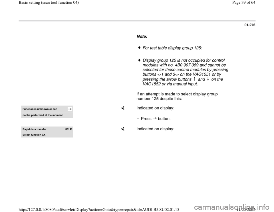
For test table display group 125:
Display group 125 is not occupied for control
modules with no. 4B0 907 389 and cannot be
selected for these control modules by pressing
buttons <-1 and 3-> on the VAG1551 or by
pressing the arrow buttons and on the
VAG1552 or via manual input.
If an attempt is made to select display group
number 125 despite this: Function is unknown or can not be performed at the moment.
Indicated on display:
-
Press button.
Rapid data transfer
HELP
Select function XX
Indicated on display:
Pa
ge 39 of 64 Basic settin
g (scan tool function 04
)
11/20/2002 htt
p://127.0.0.1:8080/audi/servlet/Dis
play?action=Goto&t
yp
e=re
pair&id=AUDI.B5.SU02.01.15
Page 40 of 64
01-277
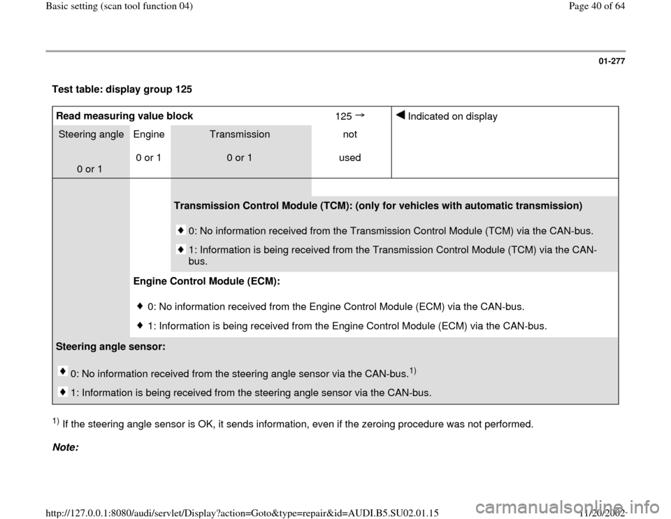
Test table: display group 125 Read measuring value block
125
Indicated on display
Steering angle
0 or 1 Engine
0 or 1
Transmission
0 or 1 not
used
Transmission Control Module (TCM): (only for vehicles with automatic transmission)
0: No information received from the Transmission Control Module (TCM) via the CAN-bus.
1: Information is being received from the Transmission Control Module (TCM) via the CAN-
bus.
Engine Control Module (ECM):
0: No information received from the Engine Control Module (ECM) via the CAN-bus.
1: Information is being received from the Engine Control Module (ECM) via the CAN-bus.
Steering angle sensor:
0: No information received from the steering angle sensor via the CAN-bus.
1)
1: Information is being received from the steering angle sensor via the CAN-bus.
1) If the steering angle sensor is OK, it sends information, even if the zeroing procedure was not performed.
Note:
Pa
ge 40 of 64 Basic settin
g (scan tool function 04
)
11/20/2002 htt
p://127.0.0.1:8080/audi/servlet/Dis
play?action=Goto&t
yp
e=re
pair&id=AUDI.B5.SU02.01.15