wiring AUDI A4 1999 B5 / 1.G Brakes ESP Electrical Testing Owner's Manual
[x] Cancel search | Manufacturer: AUDI, Model Year: 1999, Model line: A4, Model: AUDI A4 1999 B5 / 1.GPages: 65, PDF Size: 0.21 MB
Page 42 of 65
01-332
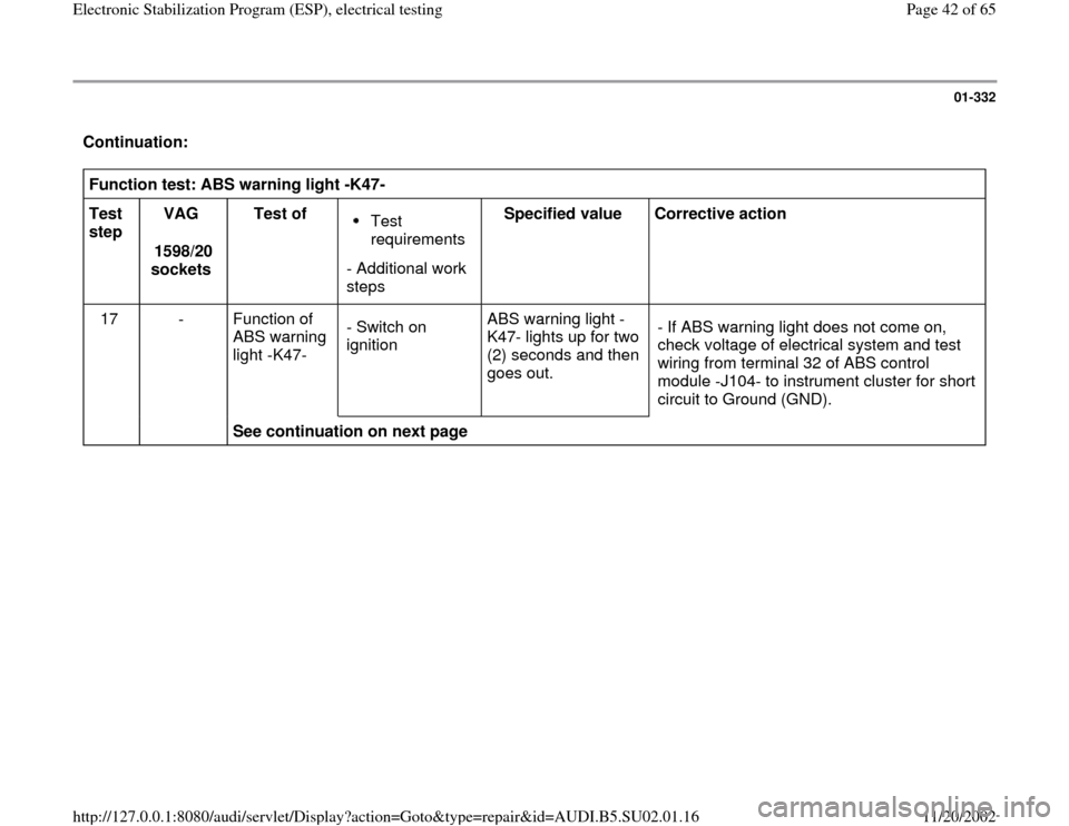
Continuation: Function test: ABS warning light -K47-
Test
step VAG
1598/20
sockets Test of
Test
requirements
- Additional work
steps Specified value
Corrective action
17 - Function of
ABS warning
light -K47- - Switch on
ignition ABS warning light -
K47- lights up for two
(2) seconds and then
goes out. - If ABS warning light does not come on,
check voltage of electrical system and test
wiring from terminal 32 of ABS control
module -J104- to instrument cluster for short
circuit to Ground (GND).
See continuation on next page
Pa
ge 42 of 65 Electronic Stabilization Pro
gram
(ESP
), electrical testin
g
11/20/2002 htt
p://127.0.0.1:8080/audi/servlet/Dis
play?action=Goto&t
yp
e=re
pair&id=AUDI.B5.SU02.01.16
Page 43 of 65
01-333
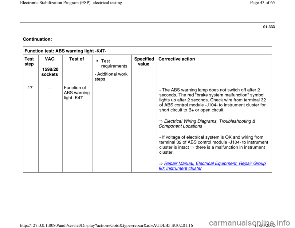
Continuation: Function test: ABS warning light -K47-
Test
step VAG
1598/20
sockets Test of
Test
requirements
- Additional work
steps Specified
value Corrective action
17 - Function of
ABS warning
light -K47-
Electrical Wiring Diagrams, Troubleshooting &
Component Locations
Repair Manual, Electrical Equipment, Repair Group
90; Instrument cluster
- The ABS warning lamp does not switch off after 2
seconds. The red "brake system malfunction" symbol
lights up after 2 seconds. Check wire from terminal 32
of ABS control module -J104- to instrument cluster for
short circuit to B+ or open circuit.
- If voltage of electrical system is OK and wiring from
terminal 32 of ABS control module -J104- to instrument
cluster is intact there is a malfunction in instrument
cluster.
Pa
ge 43 of 65 Electronic Stabilization Pro
gram
(ESP
), electrical testin
g
11/20/2002 htt
p://127.0.0.1:8080/audi/servlet/Dis
play?action=Goto&t
yp
e=re
pair&id=AUDI.B5.SU02.01.16
Page 47 of 65
01-337
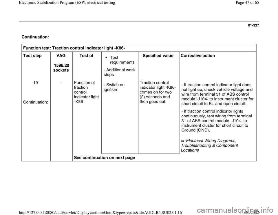
Continuation: Function test: Traction control indicator light -K86-
Test step
VAG
1598/20
sockets Test of
Test
requirements
- Additional work
steps Specified value
Corrective action
19
Continuation: - Function of
traction
control
indicator light
-K86- - Switch on
ignition Traction control
indicator light -K86-
comes on for two
(2) seconds and
then goes out.
Electrical Wiring Diagrams,
Troubleshooting & Component
Locations - If traction control indicator light does
not light up, check vehicle voltage and
wire from terminal 31 of ABS control
module -J104- to instrument cluster for
short circuit to B+ and open circuit.
- If traction control indicator lights
continuously, test wiring from terminal
31 of ABS control module -J104- to
instrument cluster for short circuit to
Ground (GND).
See continuation on next page
Pa
ge 47 of 65 Electronic Stabilization Pro
gram
(ESP
), electrical testin
g
11/20/2002 htt
p://127.0.0.1:8080/audi/servlet/Dis
play?action=Goto&t
yp
e=re
pair&id=AUDI.B5.SU02.01.16
Page 48 of 65
01-338
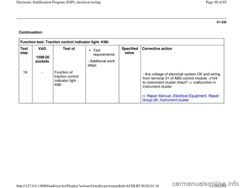
Continuation: Function test: Traction control indicator light -K86-
Test
step VAG
1598/20
sockets Test of
Test
requirements
- Additional work
steps Specified
value Corrective action
19 - Function of
traction control
indicator light -
K86-
Repair Manual, Electrical Equipment, Repair
Group 90; Instrument cluster
- Are voltage of electrical system OK and wiring
from terminal 31 of ABS control module -J104-
to instrument cluster intact? malfunction in
instrument cluster
Pa
ge 48 of 65 Electronic Stabilization Pro
gram
(ESP
), electrical testin
g
11/20/2002 htt
p://127.0.0.1:8080/audi/servlet/Dis
play?action=Goto&t
yp
e=re
pair&id=AUDI.B5.SU02.01.16
Page 51 of 65
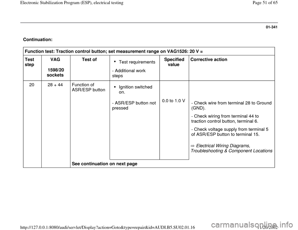
01-341
Continuation: Function test: Traction control button; set measurement range on VAG1526: 20 V =
Test
step VAG
1598/20
sockets Test of
Test requirements
- Additional work
steps Specified
value Corrective action
20 28 + 44 Function of
ASR/ESP button Ignition switched
on.
- ASR/ESP button not
pressed 0.0 to 1.0 V
Electrical Wiring Diagrams,
Troubleshooting & Component Locations
- Check wire from terminal 28 to Ground
(GND).
- Check wiring from terminal 44 to
traction control button, terminal 6.
- Check voltage supply from terminal 5
of ASR/ESP button to terminal 15.
See continuation on next page
Pa
ge 51 of 65 Electronic Stabilization Pro
gram
(ESP
), electrical testin
g
11/20/2002 htt
p://127.0.0.1:8080/audi/servlet/Dis
play?action=Goto&t
yp
e=re
pair&id=AUDI.B5.SU02.01.16
Page 52 of 65
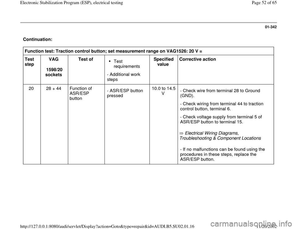
01-342
Continuation: Function test: Traction control button; set measurement range on VAG1526: 20 V =
Test
step VAG
1598/20
sockets Test of
Test
requirements
- Additional work
steps Specified
value Corrective action
20 28 + 44 Function of
ASR/ESP
button
- ASR/ESP button
pressed 10.0 to 14.5
V
Electrical Wiring Diagrams,
Troubleshooting & Component Locations - Check wire from terminal 28 to Ground
(GND).
- Check wiring from terminal 44 to traction
control button, terminal 6.
- Check voltage supply from terminal 5 of
ASR/ESP button to terminal 15.
- If no malfunctions can be found using the
procedures in these steps, replace the
ASR/ESP button.
Pa
ge 52 of 65 Electronic Stabilization Pro
gram
(ESP
), electrical testin
g
11/20/2002 htt
p://127.0.0.1:8080/audi/servlet/Dis
play?action=Goto&t
yp
e=re
pair&id=AUDI.B5.SU02.01.16
Page 53 of 65
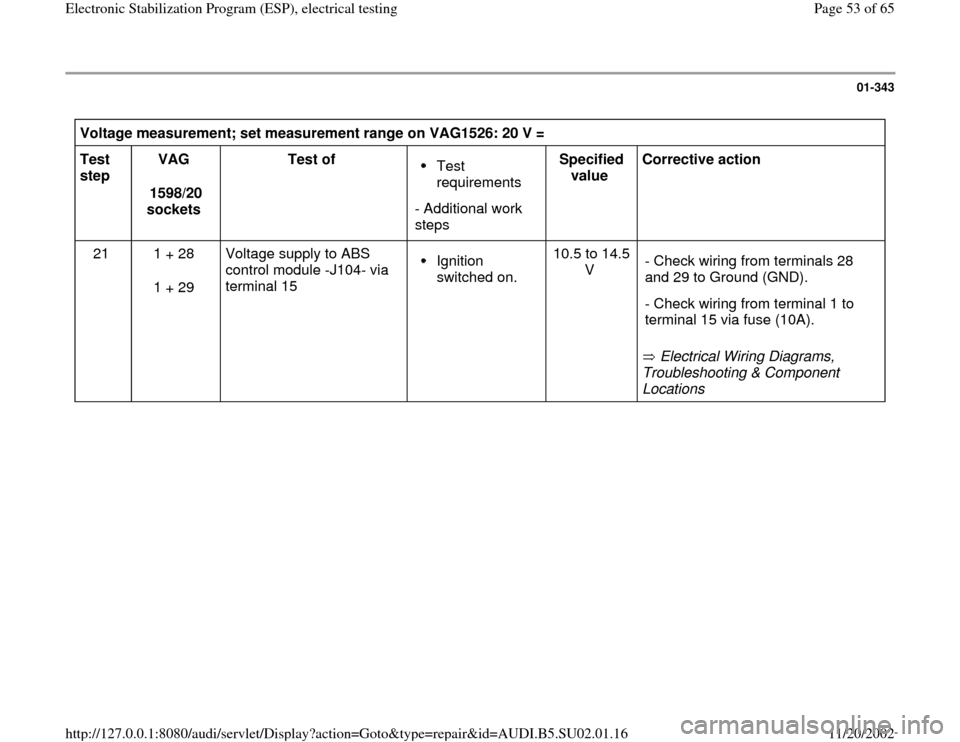
01-343
Voltage measurement; set measurement range on VAG1526: 20 V =
Test
step VAG
1598/20
sockets Test of
Test
requirements
- Additional work
steps Specified
value Corrective action
21 1 + 28
1 + 29 Voltage supply to ABS
control module -J104- via
terminal 15 Ignition
switched on. 10.5 to 14.5
V
Electrical Wiring Diagrams,
Troubleshooting & Component
Locations - Check wiring from terminals 28
and 29 to Ground (GND).
- Check wiring from terminal 1 to
terminal 15 via fuse (10A).
Pa
ge 53 of 65 Electronic Stabilization Pro
gram
(ESP
), electrical testin
g
11/20/2002 htt
p://127.0.0.1:8080/audi/servlet/Dis
play?action=Goto&t
yp
e=re
pair&id=AUDI.B5.SU02.01.16
Page 54 of 65
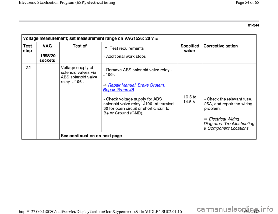
01-344
Voltage measurement; set measurement range on VAG1526: 20 V =
Test
step VAG
1598/20
sockets Test of
Test requirements
- Additional work stepsSpecified
value Corrective action
22 - Voltage supply of
solenoid valves via
ABS solenoid valve
relay -J106-.
Repair Manual, Brake System,
Repair Group 45
- Remove ABS solenoid valve relay -
J106-.
- Check voltage supply for ABS
solenoid valve relay -J106- at terminal
30 for open circuit or short circuit to
B+ or Ground (GND). 10.5 to
14.5 V
Electrical Wiring
Diagrams, Troubleshooting
& Component Locations - Check the relevant fuse,
25A, and repair the wiring
problem.
See continuation on next page
Pa
ge 54 of 65 Electronic Stabilization Pro
gram
(ESP
), electrical testin
g
11/20/2002 htt
p://127.0.0.1:8080/audi/servlet/Dis
play?action=Goto&t
yp
e=re
pair&id=AUDI.B5.SU02.01.16
Page 55 of 65

01-345
Continuation: Voltage measurement; set measurement range on VAG1526: 20 V =
Test
step VAG
1598/20
sockets Test of
Test requirements
- Additional work stepsSpecified
value Corrective action
22 - Voltage supply of
solenoid valves
via ABS solenoid
valve relay -J106-
.
- Check wiring from ABS solenoid valve
relay -J106- (terminal 87) to ABS
hydraulic unit -N55- (terminal 10) for
open circuit or short circuit to B+ or
Ground (GND).
- Fix the wiring problem.
- If the power supply lines
are OK, replace the relay.
- If the original malfunction
"ABS solenoid valve relay -
J106-" is still not fixed,
replace the ABS hydraulic
unit.
Pa
ge 55 of 65 Electronic Stabilization Pro
gram
(ESP
), electrical testin
g
11/20/2002 htt
p://127.0.0.1:8080/audi/servlet/Dis
play?action=Goto&t
yp
e=re
pair&id=AUDI.B5.SU02.01.16
Page 56 of 65
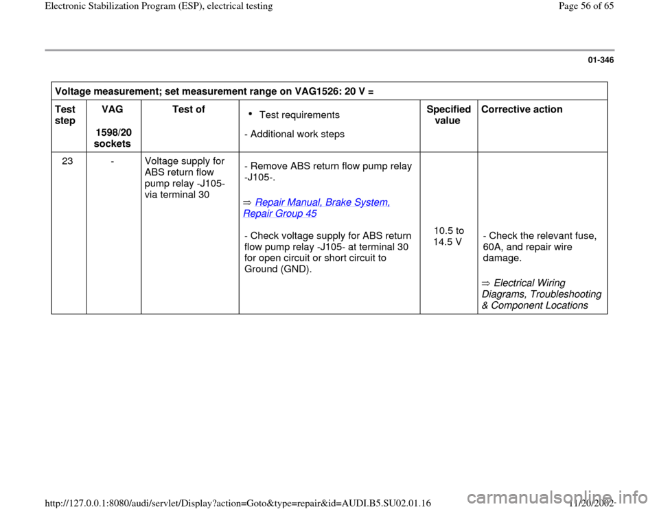
01-346
Voltage measurement; set measurement range on VAG1526: 20 V =
Test
step VAG
1598/20
sockets Test of
Test requirements
- Additional work stepsSpecified
value Corrective action
23 - Voltage supply for
ABS return flow
pump relay -J105-
via terminal 30
Repair Manual, Brake System,
Repair Group 45
- Remove ABS return flow pump relay
-J105-.
- Check voltage supply for ABS return
flow pump relay -J105- at terminal 30
for open circuit or short circuit to
Ground (GND). 10.5 to
14.5 V
Electrical Wiring
Diagrams, Troubleshooting
& Component Locations - Check the relevant fuse,
60A, and repair wire
damage.
Pa
ge 56 of 65 Electronic Stabilization Pro
gram
(ESP
), electrical testin
g
11/20/2002 htt
p://127.0.0.1:8080/audi/servlet/Dis
play?action=Goto&t
yp
e=re
pair&id=AUDI.B5.SU02.01.16