transmission AUDI A4 2000 B5 / 1.G 01V Transmission Electrical Testing Service Manual
[x] Cancel search | Manufacturer: AUDI, Model Year: 2000, Model line: A4, Model: AUDI A4 2000 B5 / 1.GPages: 66, PDF Size: 0.28 MB
Page 60 of 66
01-311
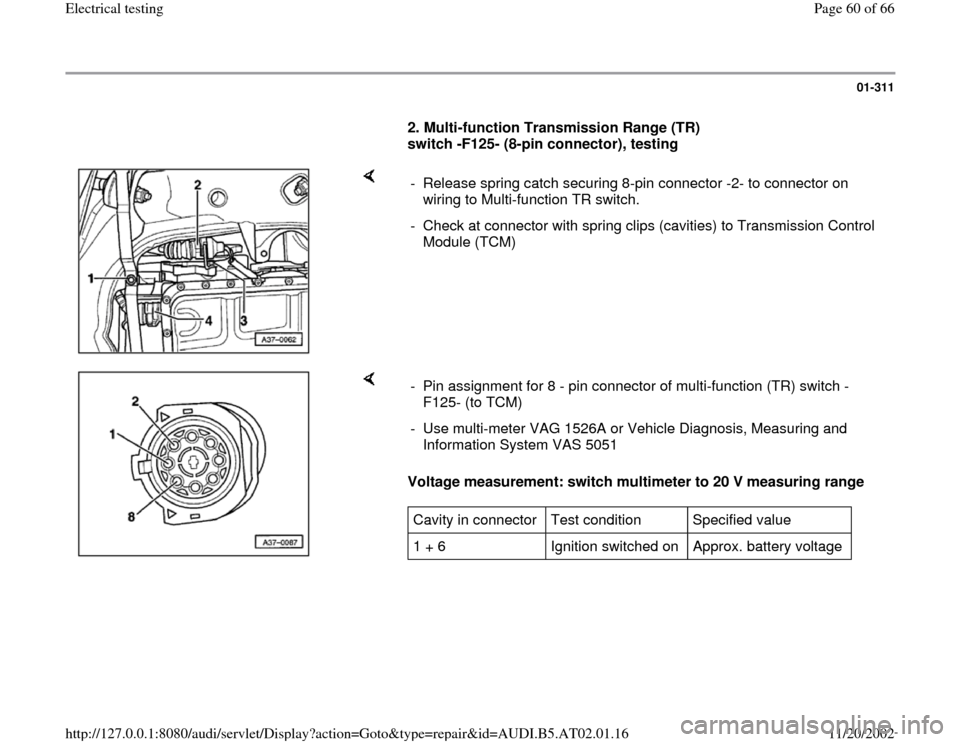
2. Multi-function Transmission Range (TR)
switch -F125- (8-pin connector), testing
- Release spring catch securing 8-pin connector -2- to connector on
wiring to Multi-function TR switch.
- Check at connector with spring clips (cavities) to Transmission Control
Module (TCM)
Voltage measurement: switch multimeter to 20 V measuring range - Pin assignment for 8 - pin connector of multi-function (TR) switch -
F125- (to TCM)
- Use multi-meter VAG 1526A or Vehicle Diagnosis, Measuring and
Information System VAS 5051 Cavity in connector Test condition Specified value
1 + 6 Ignition switched on Approx. battery voltage
Pa
ge 60 of 66 Electrical testin
g
11/20/2002 htt
p://127.0.0.1:8080/audi/servlet/Dis
play?action=Goto&t
yp
e=re
pair&id=AUDI.B5.AT02.01.16
Page 61 of 66
01-312
- If the specified value is not read, check fuses
and wiring connectors according to wiring
diagram and make necessary repairs.
Note:
If the check results and the voltage supply to the
Multi-function TR switch were OK, check wiring
connections from Transmission Control Module
(TCM) -J217- to Multi-function Transmission
Range (TR) switch page 01
-316
Pa
ge 61 of 66 Electrical testin
g
11/20/2002 htt
p://127.0.0.1:8080/audi/servlet/Dis
play?action=Goto&t
yp
e=re
pair&id=AUDI.B5.AT02.01.16
Page 62 of 66
01-313
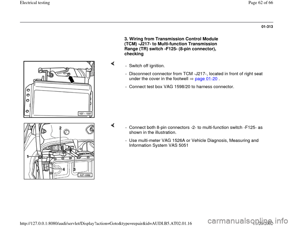
3. Wiring from Transmission Control Module
(TCM) -J217- to Multi-function Transmission
Range (TR) switch -F125- (8-pin connector),
checking
- Switch off ignition.
- Disconnect connector from TCM -J217-, located in front of right seat
under the cover in the footwell page 01
-20
.
- Connect test box VAG 1598/20 to harness connector.
- Connect both 8-pin connectors -2- to multi-function switch -F125- as
shown in the illustration.
- Use multi-meter VAG 1526A or Vehicle Diagnosis, Measuring and
Information System VAS 5051
Pa
ge 62 of 66 Electrical testin
g
11/20/2002 htt
p://127.0.0.1:8080/audi/servlet/Dis
play?action=Goto&t
yp
e=re
pair&id=AUDI.B5.AT02.01.16
Page 63 of 66
01-314
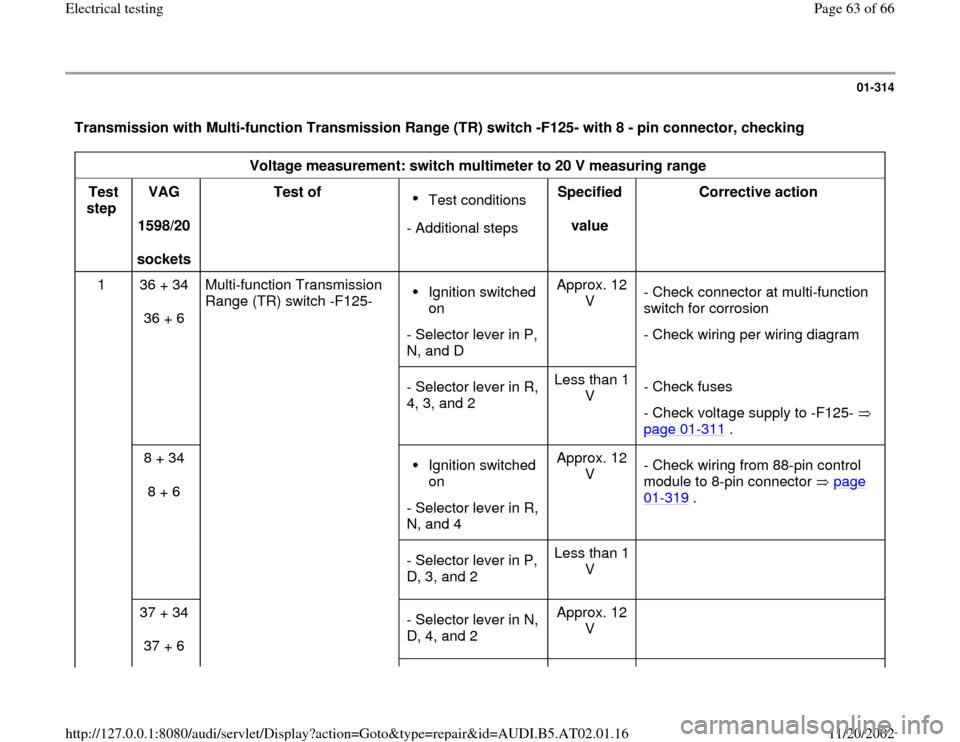
Transmission with Multi-function Transmission Range (TR) switch -F125- with 8 - pin connector, checking
Voltage measurement: switch multimeter to 20 V measuring range
Test
step VAG
1598/20
sockets Test of
Test conditions
- Additional stepsSpecified
value Corrective action
1 36 + 34
36 + 6 Multi-function Transmission
Range (TR) switch -F125- Ignition switched
on
- Selector lever in P,
N, and D Approx. 12
V - Check connector at multi-function
switch for corrosion
- Check wiring per wiring diagram
- Selector lever in R,
4, 3, and 2 Less than 1
V - Check fuses
- Check voltage supply to -F125-
page 01
-311
.
8 + 34
8 + 6
Ignition switched
on
- Selector lever in R,
N, and 4 Approx. 12
V - Check wiring from 88-pin control
module to 8-pin connector page
01
-319
.
- Selector lever in P,
D, 3, and 2 Less than 1
V
37 + 34
37 + 6
- Selector lever in N,
D, 4, and 2 Approx. 12
V
Pa
ge 63 of 66 Electrical testin
g
11/20/2002 htt
p://127.0.0.1:8080/audi/servlet/Dis
play?action=Goto&t
yp
e=re
pair&id=AUDI.B5.AT02.01.16
Page 65 of 66
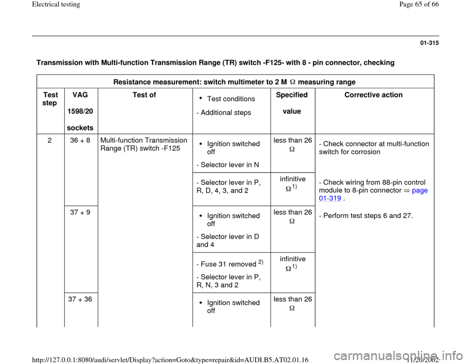
01-315
Transmission with Multi-function Transmission Range (TR) switch -F125- with 8 - pin connector, checking
Resistance measurement: switch multimeter to 2 M measuring range
Test
step VAG
1598/20
sockets Test of
Test conditions
- Additional stepsSpecified
value Corrective action
2 36 + 8
Multi-function Transmission
Range (TR) switch -F125 Ignition switched
off
- Selector lever in Nless than 26
- Check connector at multi-function
switch for corrosion
- Selector lever in P,
R, D, 4, 3, and 2 infinitive
1)
- Check wiring from 88-pin control
module to 8-pin connector page 01
-319
.
37 + 9
Ignition switched
off
- Selector lever in D
and 4 less than 26
- Perform test steps 6 and 27.
- Fuse 31 removed
2)
- Selector lever in P,
R, N, 3 and 2 infinitive
1)
37 + 36
Ignition switched
off less than 26
Pa
ge 65 of 66 Electrical testin
g
11/20/2002 htt
p://127.0.0.1:8080/audi/servlet/Dis
play?action=Goto&t
yp
e=re
pair&id=AUDI.B5.AT02.01.16