steering AUDI A4 2000 B5 / 1.G 01V Transmission Electrical Testing Workshop Manual
[x] Cancel search | Manufacturer: AUDI, Model Year: 2000, Model line: A4, Model: AUDI A4 2000 B5 / 1.GPages: 66, PDF Size: 0.28 MB
Page 41 of 66

01-298
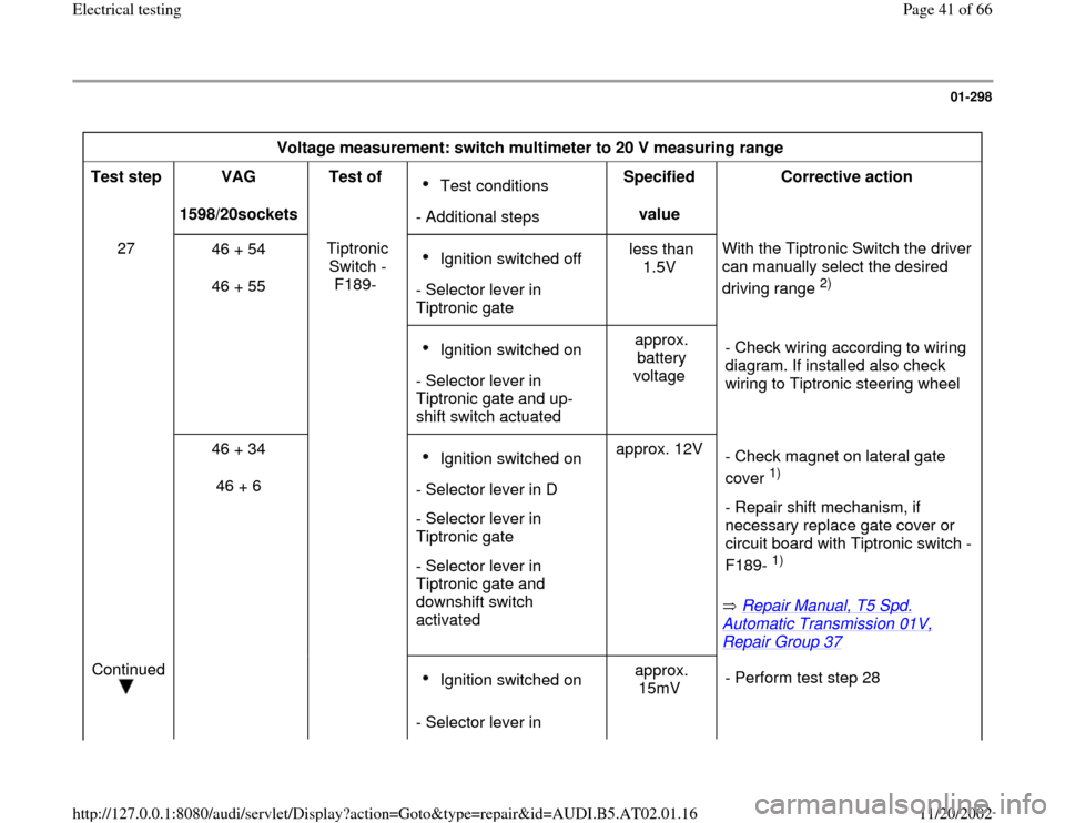
Voltage measurement: switch multimeter to 20 V measuring range
Test step
VAG
1598/20sockets Test of
Test conditions
- Additional stepsSpecified
value Corrective action
27
46 + 54
46 + 55 Tiptronic
Switch -
F189- Ignition switched off
- Selector lever in
Tiptronic gate less than
1.5V With the Tiptronic Switch the driver
can manually select the desired
driving range
2)
Ignition switched on
- Selector lever in
Tiptronic gate and up-
shift switch actuated approx.
battery
voltage - Check wiring according to wiring
diagram. If installed also check
wiring to Tiptronic steering wheel
46 + 34
46 + 6 Ignition switched on
- Selector lever in D
- Selector lever in
Tiptronic gate
- Selector lever in
Tiptronic gate and
downshift switch
activated approx. 12V
Repair Manual, T5 Spd.
Automatic Transmission 01V, Repair Group 37
- Check magnet on lateral gate
cover
1)
- Repair shift mechanism, if
necessary replace gate cover or
circuit board with Tiptronic switch -
F189- 1)
Continued
Ignition switched on
- Selector lever in approx.
15mV - Perform test step 28
Pa
ge 41 of 66 Electrical testin
g
11/20/2002 htt
p://127.0.0.1:8080/audi/servlet/Dis
play?action=Goto&t
yp
e=re
pair&id=AUDI.B5.AT02.01.16
Page 43 of 66

01-299
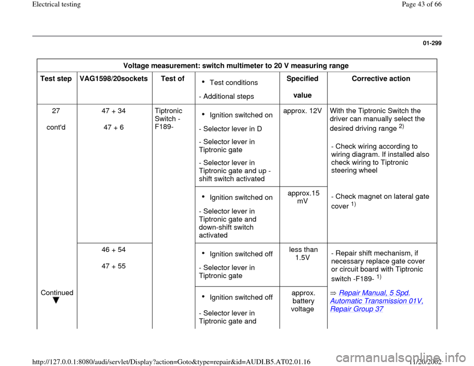
Voltage measurement: switch multimeter to 20 V measuring range
Test step
VAG1598/20sockets
Test of
Test conditions
- Additional stepsSpecified
value Corrective action
27
cont'd 47 + 34
47 + 6 Tiptronic
Switch -
F189- Ignition switched on
- Selector lever in D
- Selector lever in
Tiptronic gate
- Selector lever in
Tiptronic gate and up -
shift switch activated approx. 12V With the Tiptronic Switch the
driver can manually select the
desired driving range
2)
- Check wiring according to
wiring diagram. If installed also
check wiring to Tiptronic
steering wheel
Ignition switched on
- Selector lever in
Tiptronic gate and
down-shift switch
activated approx.15
mV - Check magnet on lateral gate
cover
1)
46 + 54
47 + 55
Ignition switched off
- Selector lever in
Tiptronic gate less than
1.5V - Repair shift mechanism, if
necessary replace gate cover
or circuit board with Tiptronic
switch -F189-
1)
Continued
Ignition switched off
- Selector lever in
Tiptronic gate and approx.
battery
voltage Repair Manual, 5 Spd.
Automatic Transmission 01V, Repair Group 37
Pa
ge 43 of 66 Electrical testin
g
11/20/2002 htt
p://127.0.0.1:8080/audi/servlet/Dis
play?action=Goto&t
yp
e=re
pair&id=AUDI.B5.AT02.01.16
Page 45 of 66

01-300
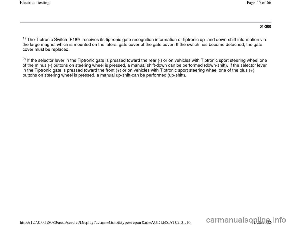
1) The Tiptronic Switch -F189- receives its tiptronic gate recognition information or tiptronic up- and down-shift information via
the large magnet which is mounted on the lateral gate cover of the gate cover. If the switch has become detached, the gate
cover must be replaced. 2) If the selector lever in the Tiptronic gate is pressed toward the rear (-) or on vehicles with Tiptronic sport steering wheel one
of the minus (-) buttons on steering wheel is pressed, a manual shift-down can be performed (down-shift). If the selector lever
in the Tiptronic gate is pressed toward the front (+) or on vehicles with Tiptronic sport steering wheel one of the plus (+)
buttons on steering wheel is pressed, a manual up-shift-can be performed (up-shift).
Pa
ge 45 of 66 Electrical testin
g
11/20/2002 htt
p://127.0.0.1:8080/audi/servlet/Dis
play?action=Goto&t
yp
e=re
pair&id=AUDI.B5.AT02.01.16