AUDI A4 2000 B5 / 1.G 01W Transmission Input Shaft User Guide
Manufacturer: AUDI, Model Year: 2000,
Model line: A4,
Model: AUDI A4 2000 B5 / 1.G
Pages: 19, PDF Size: 0.44 MB
AUDI A4 2000 B5 / 1.G 01W Transmission Input Shaft User Guide
A4 2000 B5 / 1.G
AUDI
AUDI
https://www.carmanualsonline.info/img/6/1271/w960_1271-0.png
AUDI A4 2000 B5 / 1.G 01W Transmission Input Shaft User Guide
Trending: oil, height, tow, technical data, ad blue, torque, warning
Page 11 of 19
35-8
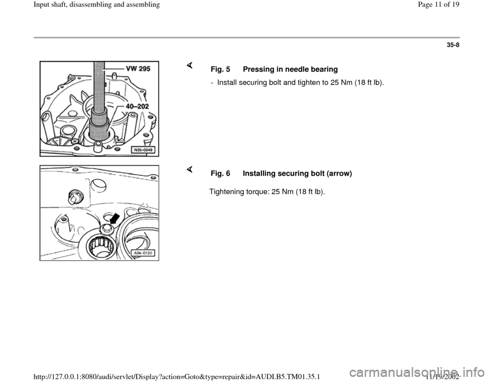
Fig. 5 Pressing in needle bearing
- Install securing bolt and tighten to 25 Nm (18 ft lb).
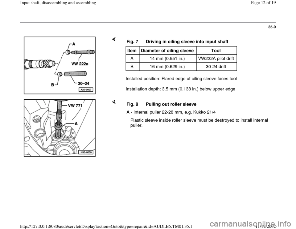
Tightening torque: 25 Nm (18 ft lb). Fig. 6 Installing securing bolt (arrow)
Pa
ge 11 of 19 In
put shaft, disassemblin
g and assemblin
g
11/19/2002 htt
p://127.0.0.1:8080/audi/servlet/Dis
play?action=Goto&t
yp
e=re
pair&id=AUDI.B5.TM01.35.1
Page 12 of 19
35-9
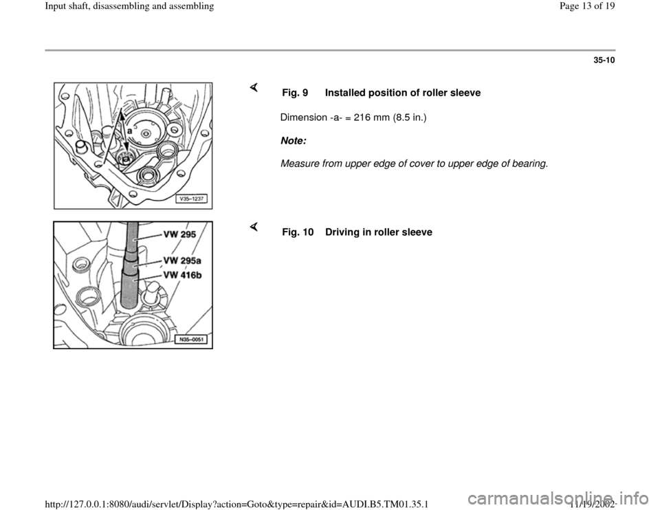
Installed position: Flared edge of oiling sleeve faces tool
Installation depth: 3.5 mm (0.138 in.) below upper edge Fig. 7 Driving in oiling sleeve into input shaftItem
Diameter of oiling sleeve
Tool
A 14 mm (0.551 in.) VW222A pilot drift
B 16 mm (0.629 in.) 30-24 drift
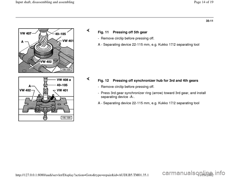
Fig. 8 Pulling out roller sleeve
A - Internal puller 22-28 mm, e.g. Kukko 21/4
Plastic sleeve inside roller sleeve must be destroyed to install internal
puller.
Pa
ge 12 of 19 In
put shaft, disassemblin
g and assemblin
g
11/19/2002 htt
p://127.0.0.1:8080/audi/servlet/Dis
play?action=Goto&t
yp
e=re
pair&id=AUDI.B5.TM01.35.1
Page 13 of 19
35-10
Dimension -a- = 216 mm (8.5 in.)
Note:
Measure from upper edge of cover to upper edge of bearing. Fig. 9 Installed position of roller sleeve
Fig. 10 Driving in roller sleeve
Pa
ge 13 of 19 In
put shaft, disassemblin
g and assemblin
g
11/19/2002 htt
p://127.0.0.1:8080/audi/servlet/Dis
play?action=Goto&t
yp
e=re
pair&id=AUDI.B5.TM01.35.1
Page 14 of 19
35-11
Fig. 11 Pressing off 5th gear
- Remove circlip before pressing off.
A - Separating device 22-115 mm, e.g. Kukko 17/2 separating tool
Fig. 12 Pressing off synchronizer hub for 3rd and 4th gears
- Remove circlip before pressing off.
- Press 3rd gear synchronizer ring (arrow) toward 3rd gear, and install
separating device -A-.
A - Separating device 22-115 mm, e.g. Kukko 17/2 separating tool
Pa
ge 14 of 19 In
put shaft, disassemblin
g and assemblin
g
11/19/2002 htt
p://127.0.0.1:8080/audi/servlet/Dis
play?action=Goto&t
yp
e=re
pair&id=AUDI.B5.TM01.35.1
Page 15 of 19
35-12
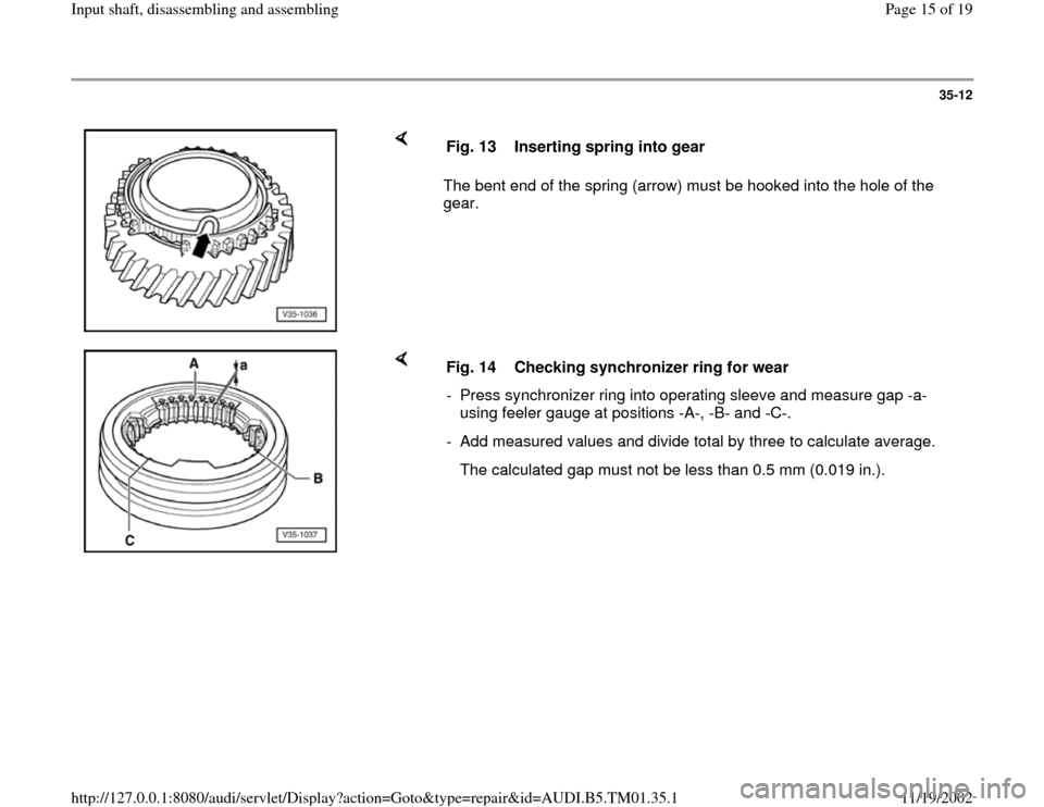
The bent end of the spring (arrow) must be hooked into the hole of the
gear. Fig. 13 Inserting spring into gear
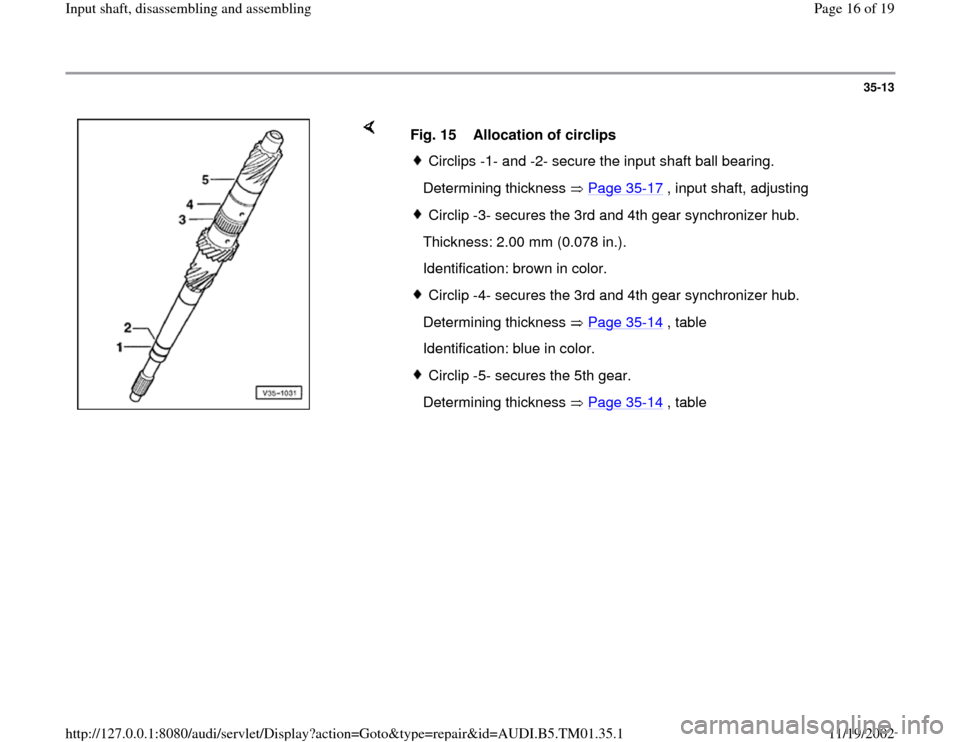
Fig. 14 Checking synchronizer ring for wear
- Press synchronizer ring into operating sleeve and measure gap -a-
using feeler gauge at positions -A-, -B- and -C-.
- Add measured values and divide total by three to calculate average.
The calculated gap must not be less than 0.5 mm (0.019 in.).
Pa
ge 15 of 19 In
put shaft, disassemblin
g and assemblin
g
11/19/2002 htt
p://127.0.0.1:8080/audi/servlet/Dis
play?action=Goto&t
yp
e=re
pair&id=AUDI.B5.TM01.35.1
Page 16 of 19
35-13
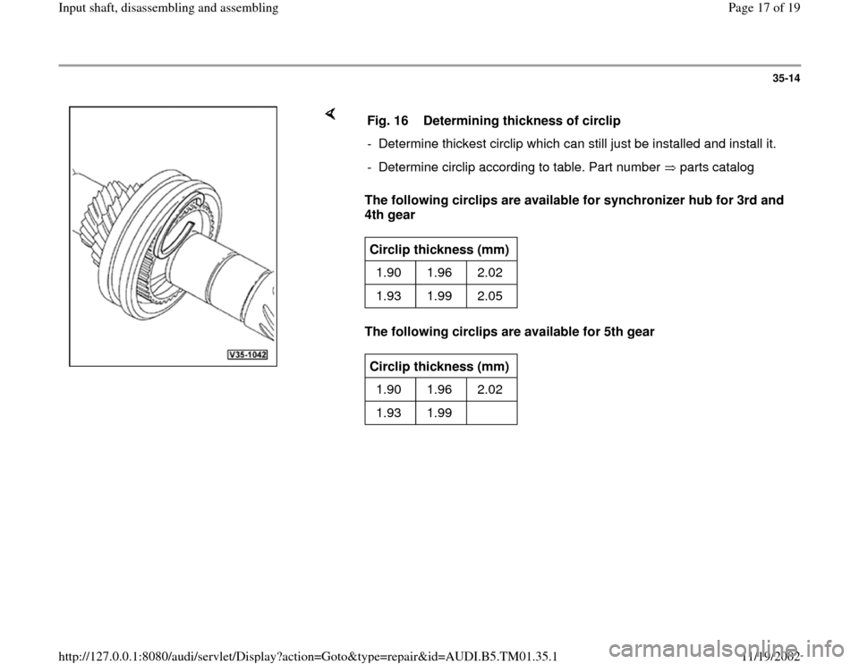
Fig. 15 Allocation of circlips
Circlips -1- and -2- secure the input shaft ball bearing.
Determining thickness Page 35
-17
, input shaft, adjusting
Circlip -3- secures the 3rd and 4th gear synchronizer hub.
Thickness: 2.00 mm (0.078 in.).
Identification: brown in color.Circlip -4- secures the 3rd and 4th gear synchronizer hub.
Determining thickness Page 35
-14
, table
Identification: blue in color.
Circlip -5- secures the 5th gear.
Determining thickness Page 35
-14
, table
Pa
ge 16 of 19 In
put shaft, disassemblin
g and assemblin
g
11/19/2002 htt
p://127.0.0.1:8080/audi/servlet/Dis
play?action=Goto&t
yp
e=re
pair&id=AUDI.B5.TM01.35.1
Page 17 of 19
35-14
The following circlips are available for synchronizer hub for 3rd and
4th gear
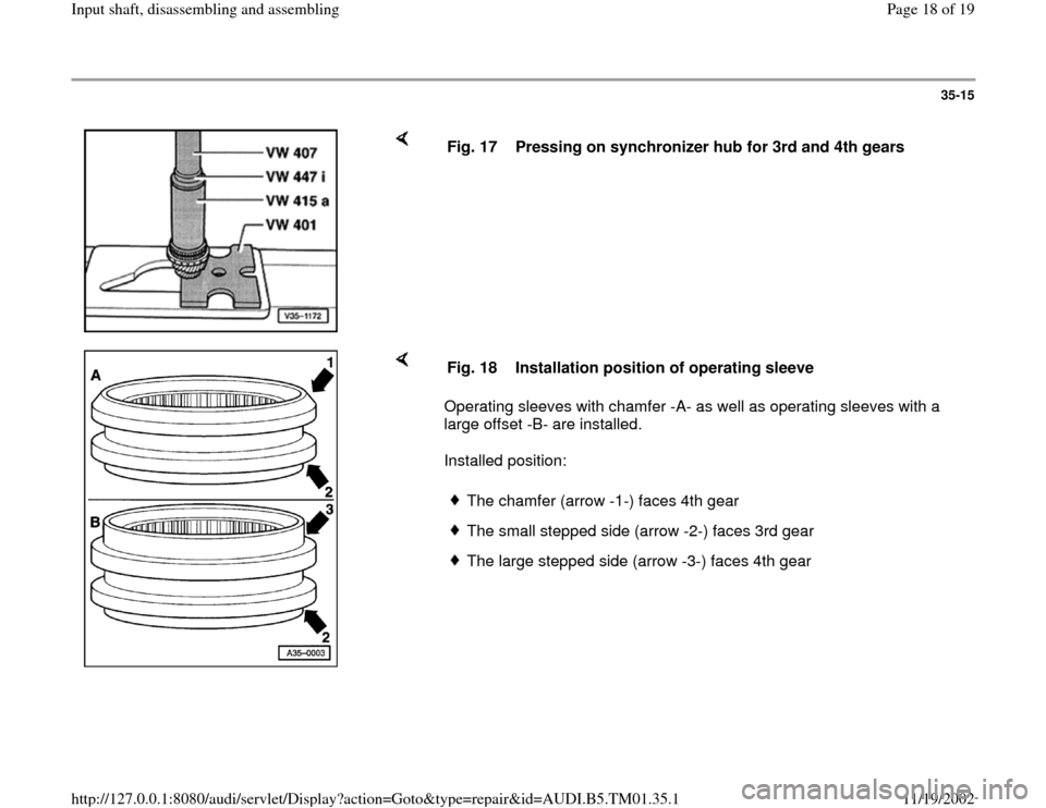
The following circlips are available for 5th gear Fig. 16 Determining thickness of circlip
- Determine thickest circlip which can still just be installed and install it.
- Determine circlip according to table. Part number parts catalogCirclip thickness (mm)
1.90 1.96 2.02
1.93 1.99 2.05 Circlip thickness (mm)
1.90 1.96 2.02
1.93 1.99
Pa
ge 17 of 19 In
put shaft, disassemblin
g and assemblin
g
11/19/2002 htt
p://127.0.0.1:8080/audi/servlet/Dis
play?action=Goto&t
yp
e=re
pair&id=AUDI.B5.TM01.35.1
Page 18 of 19
35-15
Fig. 17 Pressing on synchronizer hub for 3rd and 4th gears
Operating sleeves with chamfer -A- as well as operating sleeves with a
large offset -B- are installed.
Installed position: Fig. 18 Installation position of operating sleeve
The chamfer (arrow -1-) faces 4th gearThe small stepped side (arrow -2-) faces 3rd gearThe large stepped side (arrow -3-) faces 4th gear
Pa
ge 18 of 19 In
put shaft, disassemblin
g and assemblin
g
11/19/2002 htt
p://127.0.0.1:8080/audi/servlet/Dis
play?action=Goto&t
yp
e=re
pair&id=AUDI.B5.TM01.35.1
Page 19 of 19
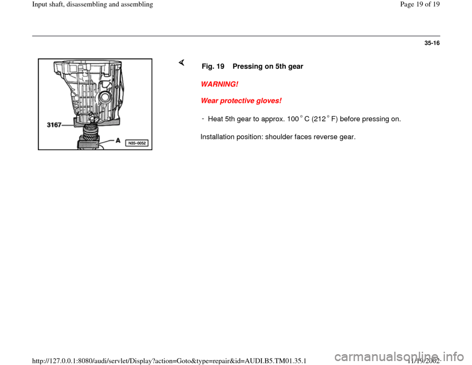
35-16
WARNING!
Wear protective gloves!
Installation position: shoulder faces reverse gear. Fig. 19 Pressing on 5th gear
-
Heat 5th gear to approx. 100 C (212 F) before pressing on.
Pa
ge 19 of 19 In
put shaft, disassemblin
g and assemblin
g
11/19/2002 htt
p://127.0.0.1:8080/audi/servlet/Dis
play?action=Goto&t
yp
e=re
pair&id=AUDI.B5.TM01.35.1
Trending: tow, ad blue, technical data, height, warning, oil, torque
