AUDI A4 2000 B5 / 1.G AC System Electrical Testing Owner's Guide
Manufacturer: AUDI, Model Year: 2000, Model line: A4, Model: AUDI A4 2000 B5 / 1.GPages: 47, PDF Size: 0.16 MB
Page 31 of 47

01-140
Test No. 3 (Fresh Air Blower -V2- and Control Module for Fresh Air Blower -J126-) Adapter cable VAG1598/11
Measuring range: Voltage measurement (20 V)
Test Step
VAG1598 socket
Test of
Test conditions
- additional work Specified Value
Corrective action
3.1 to 3.3 page 01
-124
Adapter cable VAG1598/11
LED Voltage tester VAG1527B
Test
step VAG1598
socket Test of
Test
conditions
- additional
work Specified
Value Corrective action
3.4 14 + 16 Control module for
fresh air blower -
J126-
Ignition
on - LED lights up - Diagnose and repair open circuit in
wiring between -J126- and -E87- using
wiring diagram.
- Fresh Air Blower -V2- check for ease of
movement.
- Fresh air
blower running. - Replace -J126-.
Pa
ge 31 of 47 A/C s
ystem, electrical testin
g
11/21/2002 htt
p://127.0.0.1:8080/audi/servlet/Dis
play?action=Goto&t
yp
e=re
pair&id=AUDI.B5.HA01.01.2
Page 32 of 47

01-141
Test No. 4 (air/temperature distribution flap motors and related potentiometers) Adapter cable VAG1598/12
Measuring range: Resistance measurement (20 K ) Test
Step VAG1598
socket Test of
Test
conditions
- additional
work Specified
Value Corrective action
4.1 to
4.6 page 01
-126
4.7 14 +
2
3
4
5 Short to ground of wiring to
flap motors -V68-, -V85-, -
V70-, -V71-
Ignition
off - Ohm
- Diagnose and repair short to ground in
wiring/connections using wiring diagram.
Adapter cable VAG1598/12
Measuring range: Voltage measurement (20 V)
Test
Step VAG1598
socket Test of
Test
conditions
- additional
work Specified
Value Corrective action
4.8 14 + 2
3 Short to positive of wiring to
flap motors -V68-, -V85-, -
Ignition
on - less than
1V - Diagnose and repair short to positive
in wiring/connections using wiring
Pa
ge 32 of 47 A/C s
ystem, electrical testin
g
11/21/2002 htt
p://127.0.0.1:8080/audi/servlet/Dis
play?action=Goto&t
yp
e=re
pair&id=AUDI.B5.HA01.01.2
Page 33 of 47

4
5 V70-, -V71-
diagram.
Note:
If DTC's for several flap motors are shown and malfunction is not determined in test 4, check wiring for short between
individual flap motors (e.g. -V85- and -V70-, measured value between sockets 3 and 4 must be Ohm).
Pa
ge 33 of 47 A/C s
ystem, electrical testin
g
11/21/2002 htt
p://127.0.0.1:8080/audi/servlet/Dis
play?action=Goto&t
yp
e=re
pair&id=AUDI.B5.HA01.01.2
Page 34 of 47

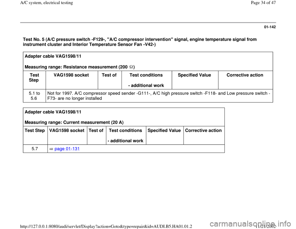
01-142
Test No. 5 (A/C pressure switch -F129-, "A/C compressor intervention" signal, engine temperature signal from
instrument cluster and Interior Temperature Sensor Fan -V42-) Adapter cable VAG1598/11
Measuring range: Resistance measurement (200 )
Test
Step VAG1598 socket
Test of
Test conditions
- additional work Specified Value
Corrective action
5.1 to
5.6 Not for 1997. A/C compressor speed sender -G111-, A/C high pressure switch -F118- and Low pressure switch -
F73- are no longer installed
Adapter cable VAG1598/11
Measuring range: Current measurement (20 A)
Test Step
VAG1598 socket
Test of
Test conditions
- additional work Specified Value
Corrective action
5.7 page 01
-131
Pa
ge 34 of 47 A/C s
ystem, electrical testin
g
11/21/2002 htt
p://127.0.0.1:8080/audi/servlet/Dis
play?action=Goto&t
yp
e=re
pair&id=AUDI.B5.HA01.01.2
Page 35 of 47

01-143
A/C control head -E87- connected to test box with adapter cable VAG1598/11
LED Voltage tester VAG1527B
Test
Step VAG1598
socket Test of
Test conditions
- additional work Specified
Value Corrective action
5.8 14 + 12 "A/C compressor
intervention"
output.
Engine
running. A/C
compressor
off
- Switch on A/C
compressor - LED lights
up
- LED lights
up slightly
dimmer. - Diagnose and repair open or short circuit in
wiring/connections using wiring diagram.
- Diagnose and eliminate A/C compressor
cut-off condition(s) from Engine Control
Module (ECM) or Transmission Control
Module (TCM)
- Diagnose and repair short circuit to ground
in wiring/connections using wiring diagram.
5.9 Ground
and
51 "Engine
temperature too
high" signal. Engine
running. - LED lights
up. - Diagnose and repair short circuit to ground
in wiring/connections using wiring diagram.
- Diagnose and eliminate A/C compressor
cut-off condition from Instrument cluster
Pa
ge 35 of 47 A/C s
ystem, electrical testin
g
11/21/2002 htt
p://127.0.0.1:8080/audi/servlet/Dis
play?action=Goto&t
yp
e=re
pair&id=AUDI.B5.HA01.01.2
Page 36 of 47

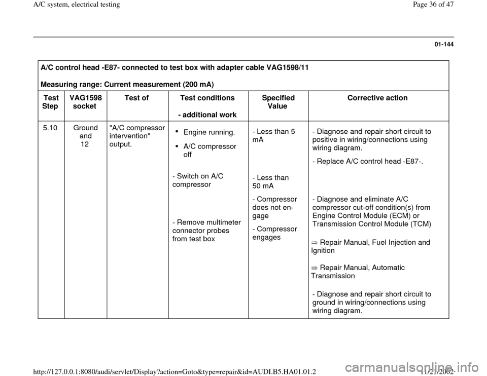
01-144
A/C control head -E87- connected to test box with adapter cable VAG1598/11
Measuring range: Current measurement (200 mA)
Test
Step VAG1598
socket Test of
Test conditions
- additional work Specified
Value Corrective action
5.10 Ground
and
12
"A/C compressor
intervention"
output.
Engine running. A/C compressor
off
- Switch on A/C
compressor
- Remove multimeter
connector probes
from test box - Less than 5
mA
- Less than
50 mA
- Compressor
does not en-
gage
- Compressor
engages
Repair Manual, Fuel Injection and
Ignition
Repair Manual, Automatic
Transmission - Diagnose and repair short circuit to
positive in wiring/connections using
wiring diagram.
- Replace A/C control head -E87-.
- Diagnose and eliminate A/C
compressor cut-off condition(s) from
Engine Control Module (ECM) or
Transmission Control Module (TCM)
- Diagnose and repair short circuit to
ground in wiring/connections using
wiring diagram.
Pa
ge 36 of 47 A/C s
ystem, electrical testin
g
11/21/2002 htt
p://127.0.0.1:8080/audi/servlet/Dis
play?action=Goto&t
yp
e=re
pair&id=AUDI.B5.HA01.01.2
Page 37 of 47

01-145
Adapter cable VAG1598/11 connected.
Measuring range: Resistance measurement (200 ) Test
Step VAG1598
socket Test of
Test
conditions
- additional
work Specified
Value Corrective action
5.11 2 + 42 A/C pressure switch -
F129- (between
terminals 1 and 2)
Ignition
off - Less than
20
- Diagnose and repair open circuit or contact
resistance in wiring/connections using wiring
diagram.1).
- Check A/C pressure switch -F129- page 87
-67
.
1) If compressor cut-off condition code 1, "A/C pressure switch -F129- open" etc. appears in read measuring value block,
display group 1, display field 1: - check for intermittent contact in wiring/connections to -F129- using wiring diagram - check
function of Coolant Fan -V7- stage 1 with Output DTM (function
03)
page 01
-42
- check A/C pressure switch -F129- function
(actuation of -V7- stage 2, terminals 3 and 4 page 87
-67
). If no fault is determined, check A/C refrigerant system pressures
page 87
-190
.
Pa
ge 37 of 47 A/C s
ystem, electrical testin
g
11/21/2002 htt
p://127.0.0.1:8080/audi/servlet/Dis
play?action=Goto&t
yp
e=re
pair&id=AUDI.B5.HA01.01.2
Page 38 of 47

01-146
Test No. 6 (A/C Clutch Relay -J44-, actuation of Coolant Fan -V7- stage 1) Adapter cable VAG1598/12 connected.
Measuring range: Amperage measurement (20 A)
Test Step
VAG1598 socket
Test of
Test conditions
- additional work Specified Value
Corrective action
6.1 + 6.2 page 01
-133
Note:
Actuation of -V7- stage 2 via A/C pressure switch -F129- page 87
-67
.
Pa
ge 38 of 47 A/C s
ystem, electrical testin
g
11/21/2002 htt
p://127.0.0.1:8080/audi/servlet/Dis
play?action=Goto&t
yp
e=re
pair&id=AUDI.B5.HA01.01.2
Page 39 of 47

01-147
Notes:
The following test steps are only performed for A/C control heads -E87- with two displays:
Teststep 2.2 (the instrument panel interior temperature sensor -G56- is installed in A/C control heads -E87- with one
display)
Test step 5.7 (the interior temperature sensor fan -V42- is installed in A/C control heads -E87- with one display)
Switch on test area at VAG1526 multimeter: voltage test (20 V =)
VAG1598/11 adapter cable connected
Test
step VAG1598A
socket Test of
Test
requirements
- additional
operations Specified
value Corrective action
1.15
4) 46 + Ground
3) Power supply
terminal 58 of A/C
control head -E87-
Ignition
switched on Park light
switched on
approx.
battery
voltage - Locate and repair open circuit or short
circuit to Ground in wiring connection to
A/C control head -E87- using wiring
diagram
1.16
4) 46 + Ground
3) Power supply
terminal 58 of A/C
control head -E87-
Ignition
switched on Park light
- Locate and repair open circuit or short
circuit to Ground in wiring connection to
A/C control head -E87- using wiring
diagram.
Pa
ge 39 of 47 A/C s
ystem, electrical testin
g
11/21/2002 htt
p://127.0.0.1:8080/audi/servlet/Dis
play?action=Goto&t
yp
e=re
pair&id=AUDI.B5.HA01.01.2
Page 40 of 47

switched off
smaller
than 2 V
3) Ground is at, for example, connector D, socket 14 and 15. 4) Only perform this test step for an A/C control head with one display.
Pa
ge 40 of 47 A/C s
ystem, electrical testin
g
11/21/2002 htt
p://127.0.0.1:8080/audi/servlet/Dis
play?action=Goto&t
yp
e=re
pair&id=AUDI.B5.HA01.01.2