coolant AUDI A4 2000 B5 / 1.G AEB ATW Engines Cylinder Head Remove And Install Workshop Manual
[x] Cancel search | Manufacturer: AUDI, Model Year: 2000, Model line: A4, Model: AUDI A4 2000 B5 / 1.GPages: 35, PDF Size: 0.68 MB
Page 1 of 35
15-2
Cylinder head, removing and
installing
Note:
Replace cylinder head bolts.
Always replace self-locking nuts, bolts as well
as gaskets and O-rings.
After installing a replacement cylinder head with
camshafts attached, grease contact surfaces
between valve lifters and cam lubricating
surfaces.
Do not remove plastic covers protecting
exposed valves until immediately before
installing cylinder head.
When replacing the cylinder head or cylinder
head gasket, coolant must be completely
replaced.
Cylinder heads with small cracks between the
valve seats that are less than 0.3 mm (0.012
in.) wide and/or between one valve seat and
only the first 4 threads of the spark plug thread,
can continue to be used without reduced
service life.
Pa
ge 1 of 35 C
ylinder head, removin
g and installin
g
11/18/2002 htt
p://127.0.0.1:8080/audi/servlet/Dis
play?action=Goto&t
yp
e=re
pair&id=AUDI.B5.GE02.15.2
Page 2 of 35
15-3
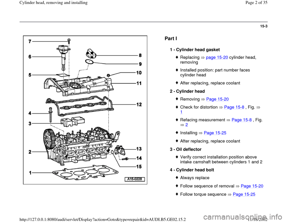
Part I
1 -
Cylinder head gasket Replacing page 15
-20
cylinder head,
removing
Installed position: part number faces
cylinder head After replacing, replace coolant
2 -
Cylinder head Removing Page 15
-20
Check for distortion Page 15
-8 , Fig.
1
Refacing measurement Page 15
-8 , Fig.
2
Installing Page 15
-25
After replacing, replace coolant
3 -
Oil deflector Verify correct installation position above
intake camshaft between cylinders 1 and 2
4 -
Cylinder head bolt Always replaceFollow sequence of removal Page 15
-20
Follow torque sequence Page 15
-25
Pa
ge 2 of 35 C
ylinder head, removin
g and installin
g
11/18/2002 htt
p://127.0.0.1:8080/audi/servlet/Dis
play?action=Goto&t
yp
e=re
pair&id=AUDI.B5.GE02.15.2
Page 4 of 35
15-5
CAUTION!
Part numbers are listed here for reference only.
Always check with your Parts department for
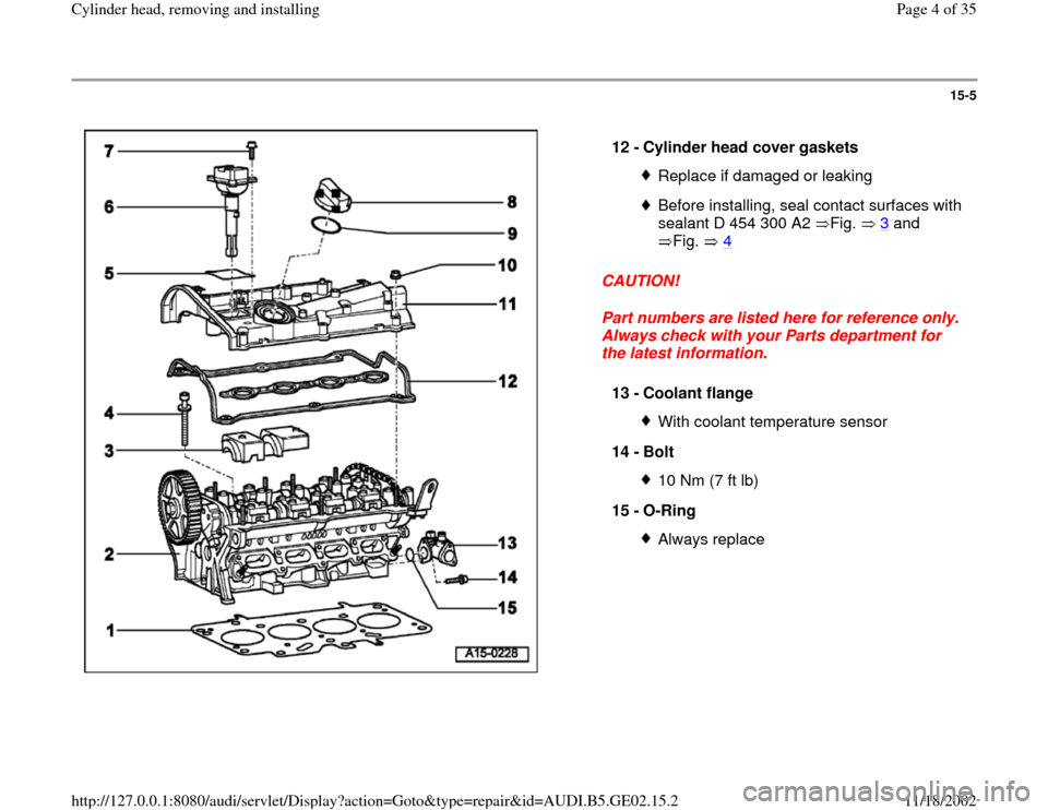
the latest information. 12 -
Cylinder head cover gaskets
Replace if damaged or leakingBefore installing, seal contact surfaces with
sealant D 454 300 A2 Fig. 3
and
Fig. 4
13 -
Coolant flange
With coolant temperature sensor
14 -
Bolt 10 Nm (7 ft lb)
15 -
O-Ring Always replace
Pa
ge 4 of 35 C
ylinder head, removin
g and installin
g
11/18/2002 htt
p://127.0.0.1:8080/audi/servlet/Dis
play?action=Goto&t
yp
e=re
pair&id=AUDI.B5.GE02.15.2
Page 5 of 35
15-6
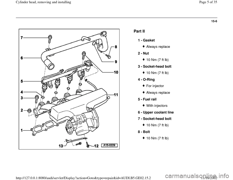
Part II
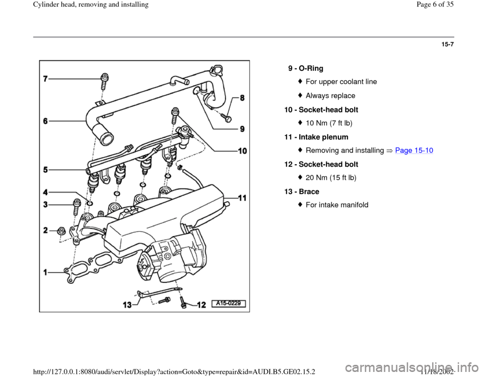
1 -
Gasket Always replace
2 -
Nut 10 Nm (7 ft lb)
3 -
Socket-head bolt 10 Nm (7 ft lb)
4 -
O-Ring For injectorAlways replace
5 -
Fuel rail With injectors
6 -
Upper coolant line
7 -
Socket-head bolt 10 Nm (7 ft lb)
8 -
Bolt 10 Nm (7 ft lb)
Pa
ge 5 of 35 C
ylinder head, removin
g and installin
g
11/18/2002 htt
p://127.0.0.1:8080/audi/servlet/Dis
play?action=Goto&t
yp
e=re
pair&id=AUDI.B5.GE02.15.2
Page 6 of 35
15-7
9 -
O-Ring
For upper coolant lineAlways replace
10 -
Socket-head bolt 10 Nm (7 ft lb)
11 -
Intake plenum Removing and installing Page 15
-10
12 -
Socket-head bolt
20 Nm (15 ft lb)
13 -
Brace For intake manifold
Pa
ge 6 of 35 C
ylinder head, removin
g and installin
g
11/18/2002 htt
p://127.0.0.1:8080/audi/servlet/Dis
play?action=Goto&t
yp
e=re
pair&id=AUDI.B5.GE02.15.2
Page 9 of 35
15-10
Intake manifold, removing and installing
Removing
Note:
All tie wraps opened or cut during removal must
be reinstalled at the same locations.
CAUTION!
BEFORE disconnecting the battery:
Stop the engine.
Be sure the ignition is switched OFF (also
applies when connecting the battery). Failure
to do so may damage the Engine Control
Module (ECM).
Determine the correct coding for the anti-
theft radio.
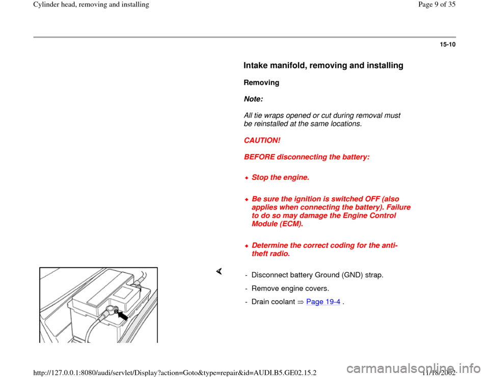
- Disconnect battery Ground (GND) strap.
- Remove engine covers.
- Drain coolant Page 19
-4 .
Pa
ge 9 of 35 C
ylinder head, removin
g and installin
g
11/18/2002 htt
p://127.0.0.1:8080/audi/servlet/Dis
play?action=Goto&t
yp
e=re
pair&id=AUDI.B5.GE02.15.2
Page 12 of 35
15-13
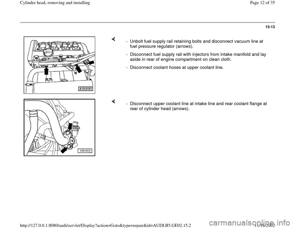
- Unbolt fuel supply rail retaining bolts and disconnect vacuum line at
fuel pressure regulator (arrows).
- Disconnect fuel supply rail with injectors from intake manifold and lay
aside in rear of engine compartment on clean cloth.
- Disconnect coolant hoses at upper coolant line.
- Disconnect upper coolant line at intake line and rear coolant flange at
rear of cylinder head (arrows).
Pa
ge 12 of 35 C
ylinder head, removin
g and installin
g
11/18/2002 htt
p://127.0.0.1:8080/audi/servlet/Dis
play?action=Goto&t
yp
e=re
pair&id=AUDI.B5.GE02.15.2
Page 14 of 35
15-15
Installing
Installation is the reverse of removal, noting the
following:
Note:
Replace gaskets and O-rings.
- Adjust Accelerator Pedal (AP) cable.
Repair Manual, Fuel Supply System, Repair
Group 20
- Top up coolant Page 19
-6 .
CAUTION!
Be sure the ignition is switched OFF. Failure
to do so may damage the Engine Control
Module (ECM).
- Switch ignition off and reconnect battery Ground
(GND) strap.
- After connecting battery, enter anti-theft code for
radio
Pa
ge 14 of 35 C
ylinder head, removin
g and installin
g
11/18/2002 htt
p://127.0.0.1:8080/audi/servlet/Dis
play?action=Goto&t
yp
e=re
pair&id=AUDI.B5.GE02.15.2
Page 16 of 35
15-16
- Perform throttle valve control module adaptation
to Engine Control Module (ECM).
Repair Manual, 1.8 Liter 5V Turbo Fuel
Injection & Ignition, Repair Group 24
Tightening torques
Component
Tightening
torques
Intake manifold to cylinder
head 10 Nm (7 ft lb)
Intake manifold brace to intake
manifold 20 Nm (15 ft lb)
Intake manifold to bracket 20 Nm (15 ft lb)
Fuel supply rail to intake
manifold 10 Nm (7 ft lb)
Coolant line to coolant flange 10 Nm (7 ft lb)
Coolant line to intake manifold 10 Nm (7 ft lb)
Pa
ge 16 of 35 C
ylinder head, removin
g and installin
g
11/18/2002 htt
p://127.0.0.1:8080/audi/servlet/Dis
play?action=Goto&t
yp
e=re
pair&id=AUDI.B5.GE02.15.2
Page 21 of 35
15-21
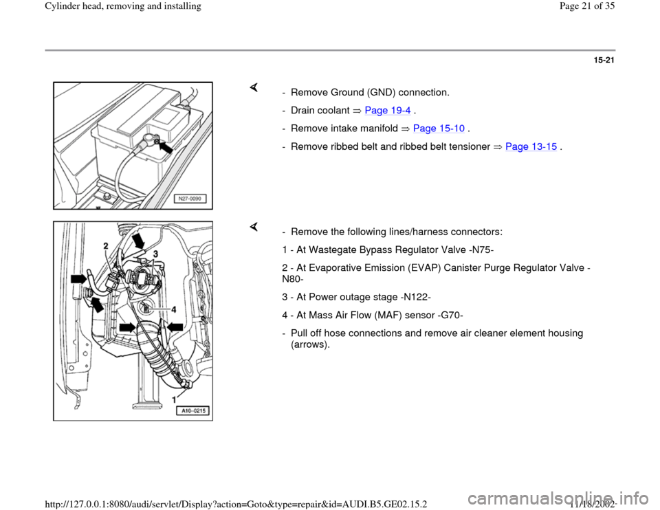
- Remove Ground (GND) connection.
- Drain coolant Page 19
-4 .
- Remove intake manifold Page 15
-10
.
- Remove ribbed belt and ribbed belt tensioner Page 13
-15
.
- Remove the following lines/harness connectors:
1 - At Wastegate Bypass Regulator Valve -N75-
2 - At Evaporative Emission (EVAP) Canister Purge Regulator Valve -
N80-
3 - At Power outage stage -N122-
4 - At Mass Air Flow (MAF) sensor -G70-
- Pull off hose connections and remove air cleaner element housing
(arrows).
Pa
ge 21 of 35 C
ylinder head, removin
g and installin
g
11/18/2002 htt
p://127.0.0.1:8080/audi/servlet/Dis
play?action=Goto&t
yp
e=re
pair&id=AUDI.B5.GE02.15.2