AUDI A4 2000 B5 / 1.G AFC Engine Auxiliary Input Signals Checking User Guide
Manufacturer: AUDI, Model Year: 2000,
Model line: A4,
Model: AUDI A4 2000 B5 / 1.G
Pages: 37, PDF Size: 0.15 MB
AUDI A4 2000 B5 / 1.G AFC Engine Auxiliary Input Signals Checking User Guide
A4 2000 B5 / 1.G
AUDI
AUDI
https://www.carmanualsonline.info/img/6/1005/w960_1005-0.png
AUDI A4 2000 B5 / 1.G AFC Engine Auxiliary Input Signals Checking User Guide
Trending: torque, turn signal, brake light, ABS, heating, automatic transmission, light
Page 11 of 37
- Replace ECM page 01
-265
.
Pa
ge 11 of 37 Auxiliar
y in
put si
gnals, checkin
g
11/22/2002 htt
p://127.0.0.1:8080/audi/servlet/Dis
play?action=Goto&t
yp
e=re
pair&id=AUDI.B5.FU01.24.25
Page 12 of 37
24-94
Engine speed (RPM) signal, checking
Notes:
The RPM signal is routed from the ECM to
various electronic systems (e.g. automatic
transmission, ABS, etc.). The RPM signal is
monitored by the different electronic systems.
Carry out the following check only if the
tachometer (in the instrument cluster) is
inoperative, or if the A/C compressor is not
running.
- Connect VAG 1367 engine-tester to tachometer
using wiring diagram.
- Connect VAG 1367 engine-tester signal wire
(green terminal) to instrument cluster RPM
terminal and A/C control module RPM terminal
(connector remains connected).
- Start engine and let idle.
RPM must be displayed again
If the specified value is obtained, the malfunction
is in instrument cluster or on A/C control module.
If the RPM is not displayed on VAG 1367 engine-
Pa
ge 12 of 37 Auxiliar
y in
put si
gnals, checkin
g
11/22/2002 htt
p://127.0.0.1:8080/audi/servlet/Dis
play?action=Goto&t
yp
e=re
pair&id=AUDI.B5.FU01.24.25
Page 13 of 37
tester:
- Check wiring between ECM terminal C10 and
instrument cluster or A/C control module using
wiring diagram.
If wiring is OK:
- Replace ECM page 01
-265
.
Pa
ge 13 of 37 Auxiliar
y in
put si
gnals, checkin
g
11/22/2002 htt
p://127.0.0.1:8080/audi/servlet/Dis
play?action=Goto&t
yp
e=re
pair&id=AUDI.B5.FU01.24.25
Page 14 of 37
24-95
Fuel consumption signal, checking
Notes:
The consumption signal is internally calculated
by the ECM using "injection time."
The consumption signal is routed to both the
trip computer and the Transmission Control
Module (TCM).
The consumption signal is monitored by the
TCM
Repair Manual, 5 Spd. Automatic
Transmission 01V, Repair Group 01; On Board Diagnostic
Carry out the following check only if DTC
memory contains a stored DTC for the TCM
related to the consumption signal, or a missing or
false consumption signal, determined during the
trip computer check.
- Remove instrument cluster or TCM.
Repair Manual, Electrical Equipment, Repair
Pa
ge 14 of 37 Auxiliar
y in
put si
gnals, checkin
g
11/22/2002 htt
p://127.0.0.1:8080/audi/servlet/Dis
play?action=Goto&t
yp
e=re
pair&id=AUDI.B5.FU01.24.25
Page 15 of 37
Group 90; Instrument cluster, repairing
Repair Manual, 5 Spd. Automatic
Transmission 01V, Repair Group 01, On Board Diagnostic
- Connect VAG 1598 test box to instrument
cluster harness connector (I/P insert not
connected) or to TCM harness connector (TCM
not connected).
Repair Manual, Electrical Equipment, Repair
Group 90; Instrument cluster, repairing
Repair Manual, 5 Spd. Automatic
Transmission 01V; Repair Group 01, On Board Diagnostic
Pa
ge 15 of 37 Auxiliar
y in
put si
gnals, checkin
g
11/22/2002 htt
p://127.0.0.1:8080/audi/servlet/Dis
play?action=Goto&t
yp
e=re
pair&id=AUDI.B5.FU01.24.25
Page 16 of 37
24-96
- Switch Fluke 83 multimeter to voltage
measurement range and connect between
signal wire (trip computer 20-pin connector) and
Ground (GND), using wiring diagram.
- Start engine and let idle.
Specified value: approx. 0.3 to 0.6 volts,
corresponding to engine speed (RPM)
- Vary engine speed continuously from 1000 to
4000 RPM.
Specified value: approx. 0.3 to 0.6 volts,
corresponding to engine speed (RPM)
If the specified value is not obtained, even
though the trip computer shows no consumption
value or there is a stored malfunction in the
TCM:
- Stop engine (switch ignition off).
- Replace trip computer and/or TCM as
required.
If the specified value is not obtained:
Pa
ge 16 of 37 Auxiliar
y in
put si
gnals, checkin
g
11/22/2002 htt
p://127.0.0.1:8080/audi/servlet/Dis
play?action=Goto&t
yp
e=re
pair&id=AUDI.B5.FU01.24.25
Page 17 of 37
If wiring OK and the specified value is not obtained: - Check wiring between ECM terminal C12 and black 20-pin trip
computer connector, using wiring diagram.
- Replace ECM page 01
-265
.
Pa
ge 17 of 37 Auxiliar
y in
put si
gnals, checkin
g
11/22/2002 htt
p://127.0.0.1:8080/audi/servlet/Dis
play?action=Goto&t
yp
e=re
pair&id=AUDI.B5.FU01.24.25
Page 18 of 37
24-97
Vehicle speed signal, checking
Note:
The vehicle speed signal originates from the
vehicle speed sensor (on the transmission) and
is routed to the instrument cluster as well as to
the Engine Control Module (ECM).
Speedometer in instrument cluster OK
Checking
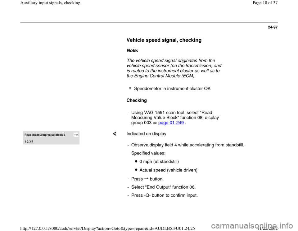
- Using VAG 1551 scan tool, select "Read
Measuring Value Block" function 08, display
group 003 page 01
-249
.
Read measuring value block 3 1 2 3 4
Indicated on display
- Observe display field 4 while accelerating from standstill.
Specified values:
0 mph (at standstill)
Actual speed (vehicle driven)
-
Press button.
- Select "End Output" function 06.
- Press -Q- button to confirm input.
Pa
ge 18 of 37 Auxiliar
y in
put si
gnals, checkin
g
11/22/2002 htt
p://127.0.0.1:8080/audi/servlet/Dis
play?action=Goto&t
yp
e=re
pair&id=AUDI.B5.FU01.24.25
Page 19 of 37
24-98
If no vehicle speed is displayed between
standstill and moving:
- Switch ignition OFF and connect VAG 1598/19
test box page 01
-255
.
- Connect VAG 1527B voltage tester between test
box sockets 13C (signal) and 10D (B+).
- Raise front of vehicle until left-front wheel is free
to rotate.
Note:
The right front wheel must NOT rotate.
- Switch ignition ON.
Voltage tester must light up at half strength
- Rotate left front wheel by hand.
Voltage tester must become brighter (flash)
If tester does not light up (become brighter) or
flash:
-
Check wiring between test box socket 13X and
Pa
ge 19 of 37 Auxiliar
y in
put si
gnals, checkin
g
11/22/2002 htt
p://127.0.0.1:8080/audi/servlet/Dis
play?action=Goto&t
yp
e=re
pair&id=AUDI.B5.FU01.24.25
Page 20 of 37
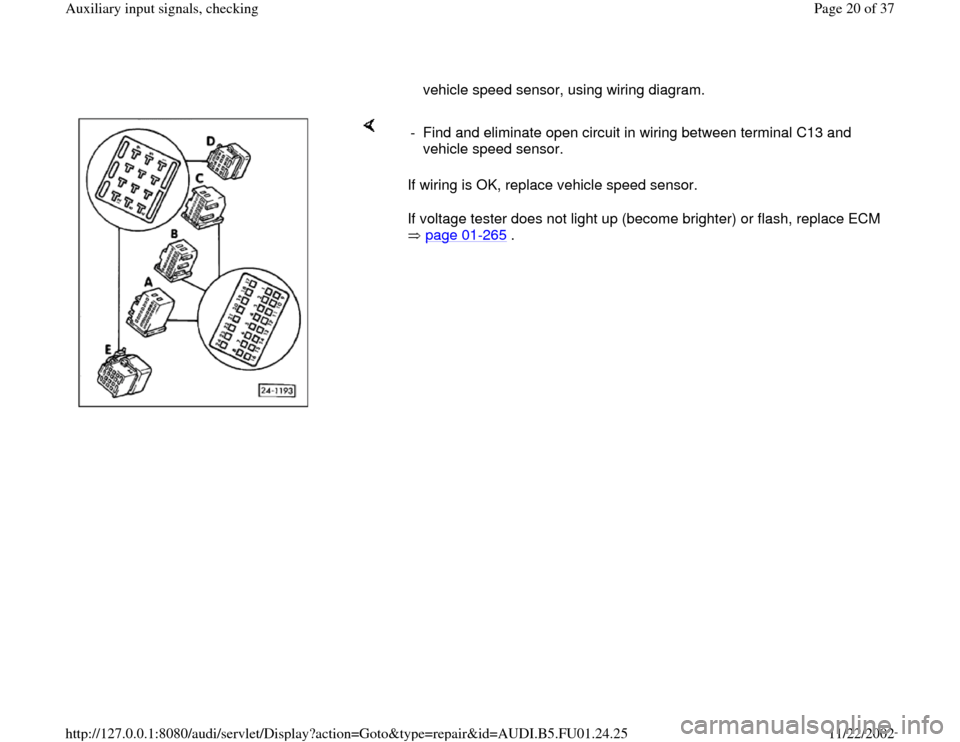
vehicle speed sensor, using wiring diagram.
If wiring is OK, replace vehicle speed sensor.
If voltage tester does not light up (become brighter) or flash, replace ECM
page 01
-265
. - Find and eliminate open circuit in wiring between terminal C13 and
vehicle speed sensor.
Pa
ge 20 of 37 Auxiliar
y in
put si
gnals, checkin
g
11/22/2002 htt
p://127.0.0.1:8080/audi/servlet/Dis
play?action=Goto&t
yp
e=re
pair&id=AUDI.B5.FU01.24.25
Trending: air condition, check engine, sensor, wiring diagram, manual transmission, instrument cluster, check engine light
