ignition AUDI A4 2000 B5 / 1.G APB Engine Motronic Syst
[x] Cancel search | Manufacturer: AUDI, Model Year: 2000, Model line: A4, Model: AUDI A4 2000 B5 / 1.GPages: 166, PDF Size: 0.53 MB
Page 59 of 166

01-49
DTC
Description of malfunction
Corrective action
SAE
VAG
P1361 17769 Cyl. 3, ignition circuit
Open Circuit
2) - Check activation of power output stages Page 28
-11
P1362 17770 Cyl. 3, ignition circuit
Short to B+
2)
P1363 17771 Cyl. 3, ignition circuit
Short to ground
2)
P1364 17772 Cyl. 4, ignition circuit
Open Circuit
2)
P1365 17773 Cyl. 4, ignition circuit
Short Circuit to B+
2)
P1366 17774 Cyl. 4, ignition circuit
Short Circuit to ground
2)
2) With this malfunction the exhaust Malfunction Indicator Light (MIL) is only switched on by the ECM, if the malfunction is
recognized after the engine has been restarted. Significance of MIL Page 01
-3 .
Pa
ge 59 of 166 Motronic s
ystem, On Board Dia
gnostic
(OBD
)
11/22/2002 htt
p://127.0.0.1:8080/audi/servlet/Dis
play?action=Goto&t
yp
e=re
pair&id=AUDI.B5.FU04.01.1
Page 60 of 166

01-50
DTC
Description of malfunction
Corrective action
SAE
VAG
P1367 17775 Cyl. 5, ignition circuit
Open Circuit
2) - Check activation of power output stages Page 28
-11
P1368 17776 Cyl. 5, ignition circuit
Short to B+
2)
P1369 17777 Cyl. 5, ignition circuit
Short to ground
2)
P1370 17778 Cyl. 6, ignition circuit
Open Circuit
2)
P1371 17779 Cyl. 6, ignition circuit
Short Circuit to B+
2)
P1372 17780 Cyl. 6, ignition circuit
Short Circuit to ground
2)
2) With this malfunction the exhaust Malfunction Indicator Light (MIL) is only switched on by the ECM, if the malfunction is
recognized after the engine has been restarted. Significance of MIL Page 01
-3 .
Pa
ge 60 of 166 Motronic s
ystem, On Board Dia
gnostic
(OBD
)
11/22/2002 htt
p://127.0.0.1:8080/audi/servlet/Dis
play?action=Goto&t
yp
e=re
pair&id=AUDI.B5.FU04.01.1
Page 92 of 166

01-75
Output Diagnostic Test Mode (DTM)
Notes:
The DTM can only be performed with the
ignition switched on and the engine not running.
The DTM is terminated if the engine is started
or if an engine speed pulse is detected.
During the DTM, individual control elements will
be activated for approx. 1 minute, or until the
test program is advanced to the next control
element by pressing the button.
The control elements can be tested either by
listening or by touching.
If the DTM is to be repeated, the engine must
be started. The engine control module needs to
detect an engine speed of more than 300 rpm.
The electric fuel pump runs continuously
throughout the DTM.
Pa
ge 92 of 166 Motronic s
ystem, On Board Dia
gnostic
(OBD
)
11/22/2002 htt
p://127.0.0.1:8080/audi/servlet/Dis
play?action=Goto&t
yp
e=re
pair&id=AUDI.B5.FU04.01.1
Page 95 of 166

01-77
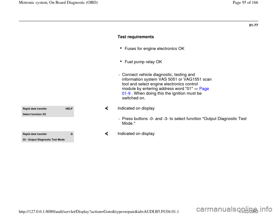
Test requirements
Fuses for engine electronics OK
Fuel pump relay OK
- Connect vehicle diagnostic, testing and
information system VAS 5051 or VAG1551 scan
tool and select engine electronics control
module by entering address word "01" Page 01
-9 . When doing this the ignition must be
switched on.
Rapid data transfer
HELP
Select function XX
Indicated on display
- Press buttons -0- and -3- to select function "Output Diagnostic Test
Mode."
Rapid data transfer
Q
03 - Output Dia
gnostic Test Mode
Indicated on display
Pa
ge 95 of 166 Motronic s
ystem, On Board Dia
gnostic
(OBD
)
11/22/2002 htt
p://127.0.0.1:8080/audi/servlet/Dis
play?action=Goto&t
yp
e=re
pair&id=AUDI.B5.FU04.01.1
Page 105 of 166

01-87
Output Diagnostic Test Mode END
Indicated on display
-
Press button.
Rapid data transfer
HELP
Select function XX
Indicated on display (function selection):
Note:
The output Diagnostic Test Mode (DTM) cannot be re-initiated until the
engine is started and ignition switched off and then on again.
Pa
ge 105 of 166 Motronic s
ystem, On Board Dia
gnostic
(OBD
)
11/22/2002 htt
p://127.0.0.1:8080/audi/servlet/Dis
play?action=Goto&t
yp
e=re
pair&id=AUDI.B5.FU04.01.1
Page 106 of 166

01-88
Basic setting
With the ignition on and engine not running,
the following operation can be performed in
the "Basic setting" mode (function 04):
Adaptation of throttle valve control module to
ECM Page 24
-146
Vehicles with automatic transmission:
Adaptation of kick down function of accelerator
pedal position sensor to ECM Display group
63 ( Page 24
-166
)
With the engine running, the following
operations can be performed in the basic
setting mode "Function 04":
Learning process (adaptation) for oxygen
sensor control every display group
Troubleshooting by targeted activation and
deactivation of oxygen sensor control display
group 99 (Observe note on page Page 24
-
81
).
Pa
ge 106 of 166 Motronic s
ystem, On Board Dia
gnostic
(OBD
)
11/22/2002 htt
p://127.0.0.1:8080/audi/servlet/Dis
play?action=Goto&t
yp
e=re
pair&id=AUDI.B5.FU04.01.1
Page 113 of 166

01-93
Control module, coding
Notes:
If the correct coding for the vehicle is not
displayed, or if the control module has been
replaced, the control module must be coded.
- Connect vehicle diagnostic, testing and
information system VAS 5051 or VAG1551 scan
tool and select engine electronics control
module by entering address word "01" Page 01
-9 . When doing this the ignition must be
switched on.
8D0907551.. 2.7L V6/5VT
G 0002
Codin
g 06711
WSC 06388
The display of VAG1551 will show the control module coding (example).
The relevant vehicle coding must be displayed, note coding table Page 01
-94
.
Pa
ge 113 of 166 Motronic s
ystem, On Board Dia
gnostic
(OBD
)
11/22/2002 htt
p://127.0.0.1:8080/audi/servlet/Dis
play?action=Goto&t
yp
e=re
pair&id=AUDI.B5.FU04.01.1
Page 122 of 166

01-101
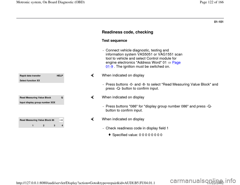
Readiness code, checking
Test sequence
- Connect vehicle diagnostic, testing and
information system VAS5051 or VAG1551 scan
tool to vehicle and select Control module for
engine electronics "Address Word" 01 Page
01
-9 . The ignition must be switched on.
Rapid data transfer
HELP
Select function XX
When indicated on display
- Press buttons -0- and -8- to select "Read Measuring Value Block" and
press -Q- button to confirm input.
Read Measurin
g Value Block
Q
Input displa
y group number XXX
When indicated on display
- Press buttons "086" for "display group number 086" and press -Q-
button to confirm input.
Read Measuring Value Block 86
1
2
3
4
When indicated on display
- Check readiness code in display field 1
Specified value: 0 0 0 0 0 0 0 0
Pa
ge 122 of 166 Motronic s
ystem, On Board Dia
gnostic
(OBD
)
11/22/2002 htt
p://127.0.0.1:8080/audi/servlet/Dis
play?action=Goto&t
yp
e=re
pair&id=AUDI.B5.FU04.01.1
Page 128 of 166

01-106
Work step 1: Check DTC memory
- Connect Vehicle Diagnostic, Test and
Information system VAS5051 or VAG1551 scan
tool to vehicle and select control module for
engine electronics using "address word" 01
Page 01
-9 . The ignition is switched on.
Rapid data transfer
HELP
Select function XX
When indicated on display
- Press buttons -0- and -2- to select function "Check DTC Memory" and
press -Q- button to confirm input.
X DTC reco
gnized!
Number of stored DTCs or "No DTC recognized" will be indicated on
display.
If a DTC is stored:
If no DTC is stored: - Repair malfunction, erase DTC memory. Road test vehicle and then re-
check DTC memory as a control measure.
-
Press button.
Pa
ge 128 of 166 Motronic s
ystem, On Board Dia
gnostic
(OBD
)
11/22/2002 htt
p://127.0.0.1:8080/audi/servlet/Dis
play?action=Goto&t
yp
e=re
pair&id=AUDI.B5.FU04.01.1
Page 129 of 166

01-107
Work step 2: Erase DTC Memory
Test requirements
Ignition switched on
Rapid data transfer
HELP
Select function XX
When indicated on display
Note:
When DTC memory is erased, readiness code is reset and must therefore
be re-generated. - Press button -0- and -5- to select function "Erase DTC Memory" and
press -Q- button to confirm input.
Rapid data transfer DTC memor
y is erased
When indicated on display
-
Press button.
Pa
ge 129 of 166 Motronic s
ystem, On Board Dia
gnostic
(OBD
)
11/22/2002 htt
p://127.0.0.1:8080/audi/servlet/Dis
play?action=Goto&t
yp
e=re
pair&id=AUDI.B5.FU04.01.1