ignition AUDI A4 2000 B5 / 1.G APB Engine Motronic Syst
[x] Cancel search | Manufacturer: AUDI, Model Year: 2000, Model line: A4, Model: AUDI A4 2000 B5 / 1.GPages: 166, PDF Size: 0.53 MB
Page 4 of 166
01-4
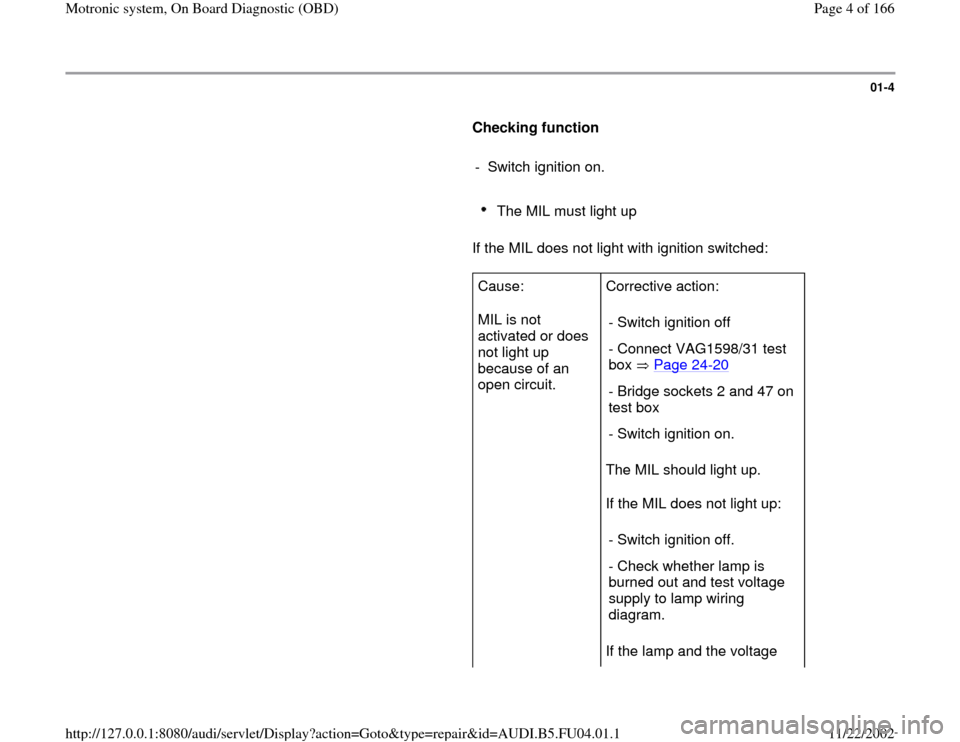
Checking function
- Switch ignition on.
The MIL must light up
If the MIL does not light with ignition switched:
Cause:
MIL is not
activated or does
not light up
because of an
open circuit. Corrective action:
The MIL should light up.
If the MIL does not light up:
If the lamp and the voltage - Switch ignition off
- Connect VAG1598/31 test
box Page 24
-20
- Bridge sockets 2 and 47 on
test box
- Switch ignition on.
- Switch ignition off.
- Check whether lamp is
burned out and test voltage
supply to lamp wiring
diagram.
Pa
ge 4 of 166 Motronic s
ystem, On Board Dia
gnostic
(OBD
)
11/22/2002 htt
p://127.0.0.1:8080/audi/servlet/Dis
play?action=Goto&t
yp
e=re
pair&id=AUDI.B5.FU04.01.1
Page 6 of 166
01-5
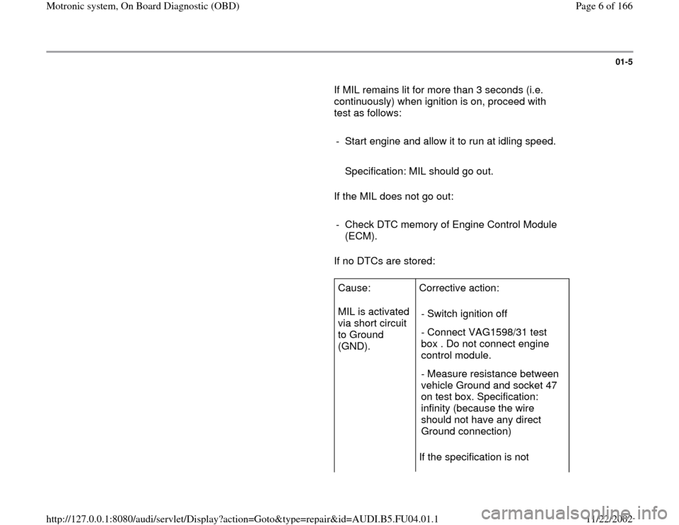
If MIL remains lit for more than 3 seconds (i.e.
continuously) when ignition is on, proceed with
test as follows:
- Start engine and allow it to run at idling speed.
Specification: MIL should go out.
If the MIL does not go out:
- Check DTC memory of Engine Control Module
(ECM).
If no DTCs are stored:
Cause:
MIL is activated
via short circuit
to Ground
(GND). Corrective action:
If the specification is not - Switch ignition off
- Connect VAG1598/31 test
box . Do not connect engine
control module.
- Measure resistance between
vehicle Ground and socket 47
on test box. Specification:
infinity (because the wire
should not have any direct
Ground connection)
Pa
ge 6 of 166 Motronic s
ystem, On Board Dia
gnostic
(OBD
)
11/22/2002 htt
p://127.0.0.1:8080/audi/servlet/Dis
play?action=Goto&t
yp
e=re
pair&id=AUDI.B5.FU04.01.1
Page 8 of 166
01-6
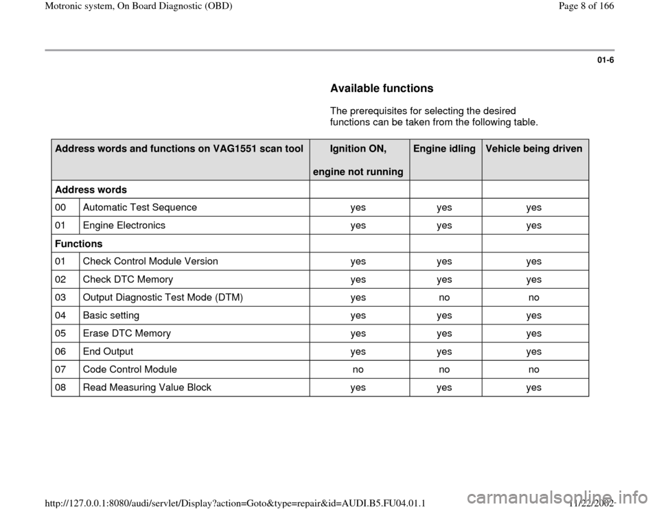
Available functions
The prerequisites for selecting the desired
functions can be taken from the following table.
Address words and functions on VAG1551 scan tool
Ignition ON,
engine not running
Engine idling
Vehicle being driven
Address words
00 Automatic Test Sequence yes yes yes
01 Engine Electronics yes yes yes
Functions
01 Check Control Module Version yes yes yes
02 Check DTC Memory yes yes yes
03 Output Diagnostic Test Mode (DTM) yes no no
04 Basic setting yes yes yes
05 Erase DTC Memory yes yes yes
06 End Output yes yes yes
07 Code Control Module no no no
08 Read Measuring Value Block yes yes yes
Pa
ge 8 of 166 Motronic s
ystem, On Board Dia
gnostic
(OBD
)
11/22/2002 htt
p://127.0.0.1:8080/audi/servlet/Dis
play?action=Goto&t
yp
e=re
pair&id=AUDI.B5.FU04.01.1
Page 9 of 166
01-7
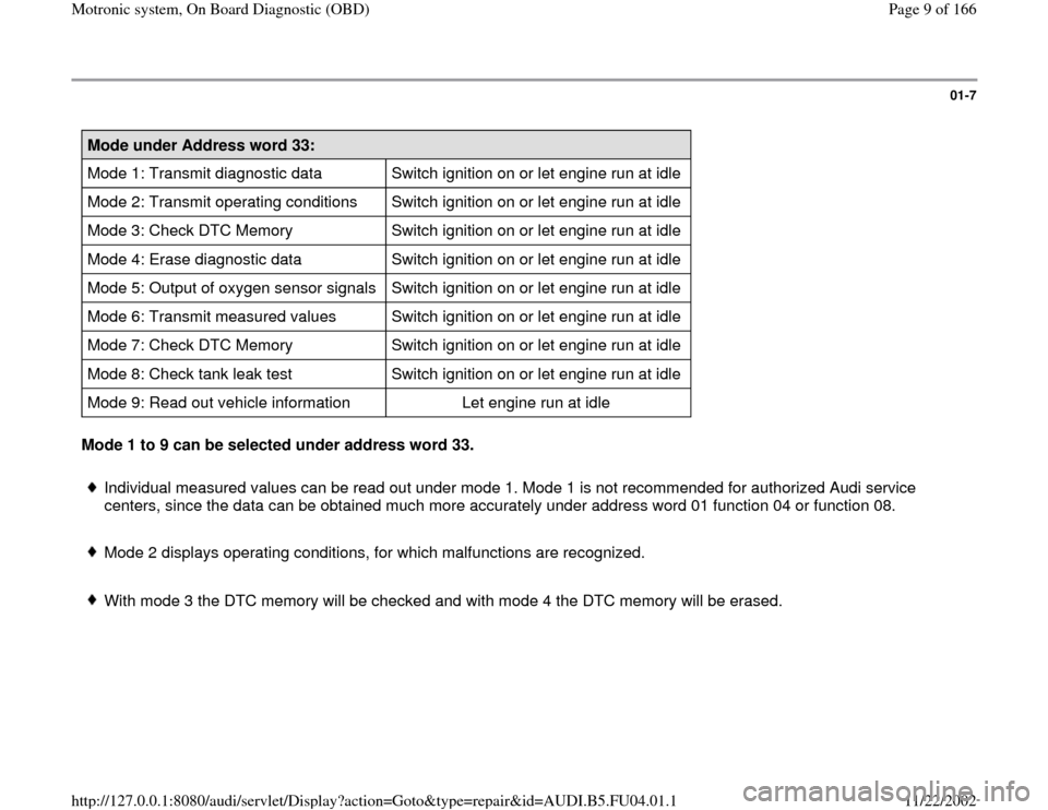
Mode under Address word 33:
Mode 1: Transmit diagnostic data Switch ignition on or let engine run at idle
Mode 2: Transmit operating conditions Switch ignition on or let engine run at idle
Mode 3: Check DTC Memory Switch ignition on or let engine run at idle
Mode 4: Erase diagnostic data Switch ignition on or let engine run at idle
Mode 5: Output of oxygen sensor signals Switch ignition on or let engine run at idle
Mode 6: Transmit measured values Switch ignition on or let engine run at idle
Mode 7: Check DTC Memory Switch ignition on or let engine run at idle
Mode 8: Check tank leak test Switch ignition on or let engine run at idle
Mode 9: Read out vehicle information Let engine run at idle Mode 1 to 9 can be selected under address word 33.
Individual measured values can be read out under mode 1. Mode 1 is not recommended for authorized Audi service
centers, since the data can be obtained much more accurately under address word 01 function 04 or function 08.
Mode 2 displays operating conditions, for which malfunctions are recognized.
With mode 3 the DTC memory will be checked and with mode 4 the DTC memory will be erased.
Pa
ge 9 of 166 Motronic s
ystem, On Board Dia
gnostic
(OBD
)
11/22/2002 htt
p://127.0.0.1:8080/audi/servlet/Dis
play?action=Goto&t
yp
e=re
pair&id=AUDI.B5.FU04.01.1
Page 11 of 166
01-9
Vehicle diagnostic, testing and
information system VAS5051 or
VAG1551, connecting and selecting
functions
Requirements
Fuses for engine electronics OK
Fuel pump relay OK
Battery voltage at least 11 V
Ground (GND) connection for engine and
transmission OK
- Switch ignition off.
Note:
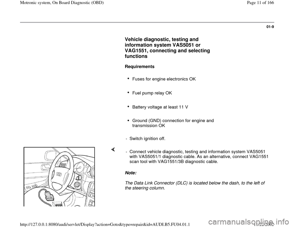
The Data Link Connector (DLC) is located below the dash, to the left of
the steering column. - Connect vehicle diagnostic, testing and information system VAS5051
with VAS5051/1 diagnostic cable. As an alternative, connect VAG1551
scan tool with VAG1551/3B diagnostic cable.
Pa
ge 11 of 166 Motronic s
ystem, On Board Dia
gnostic
(OBD
)
11/22/2002 htt
p://127.0.0.1:8080/audi/servlet/Dis
play?action=Goto&t
yp
e=re
pair&id=AUDI.B5.FU04.01.1
Page 13 of 166
01-11
- If no display appears, check diagnostic
cables:
Electrical Wiring Diagrams, Troubleshooting &
Component Locations Depending on the function required:
- Switch ignition on.
or
Start engine Page 01
-6 , table of available
functions.
- Switch on printer with PRINT button (indicator
light in button lights up).
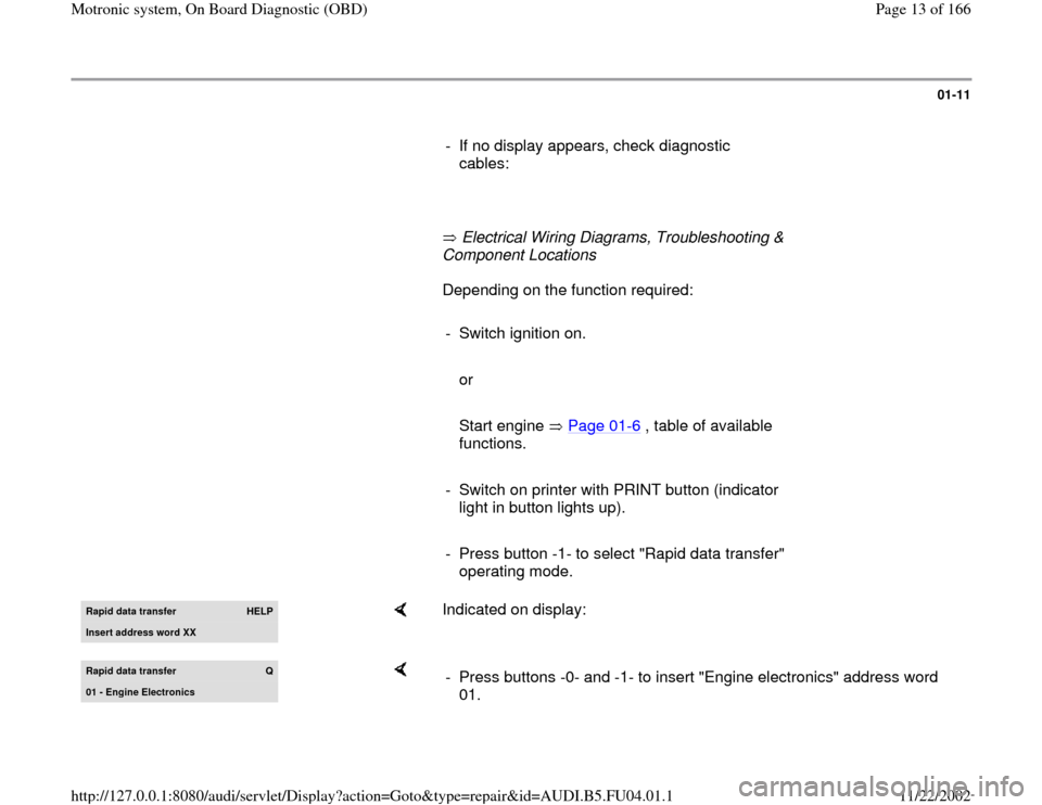
- Press button -1- to select "Rapid data transfer"
operating mode. Rapid data transfer
HELP
Insert address word XX
Indicated on display:
Rapid data transfer
Q
01 - En
gine Electronics
- Press buttons -0- and -1- to insert "Engine electronics" address word
01.
Pa
ge 13 of 166 Motronic s
ystem, On Board Dia
gnostic
(OBD
)
11/22/2002 htt
p://127.0.0.1:8080/audi/servlet/Dis
play?action=Goto&t
yp
e=re
pair&id=AUDI.B5.FU04.01.1
Page 18 of 166
01-15
Diagnostic Trouble Code (DTC) Memory,
checking and erasing
- Connect vehicle diagnostic, testing and
information system VAS5051 or VAG1551 scan
tool and select "Engine Electronics" by entering
address word 01 Page 01
-9. When doing this
the engine must be idling.
Only if engine does not start:
- Check engine with ignition switched on.
- Switch on printer with PRINT button (indicator
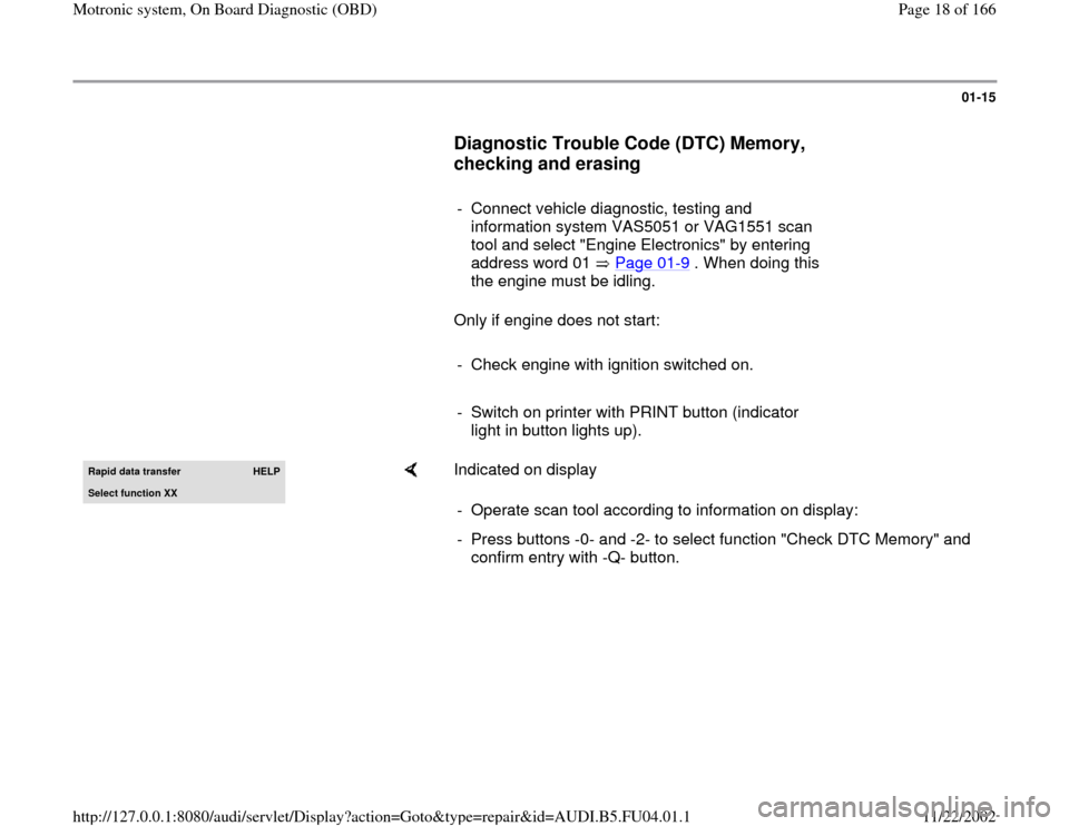
light in button lights up). Rapid data transfer
HELP
Select function XX
Indicated on display
- Operate scan tool according to information on display:
- Press buttons -0- and -2- to select function "Check DTC Memory" and
confirm entry with -Q- button.
Pa
ge 18 of 166 Motronic s
ystem, On Board Dia
gnostic
(OBD
)
11/22/2002 htt
p://127.0.0.1:8080/audi/servlet/Dis
play?action=Goto&t
yp
e=re
pair&id=AUDI.B5.FU04.01.1
Page 20 of 166
01-17
-
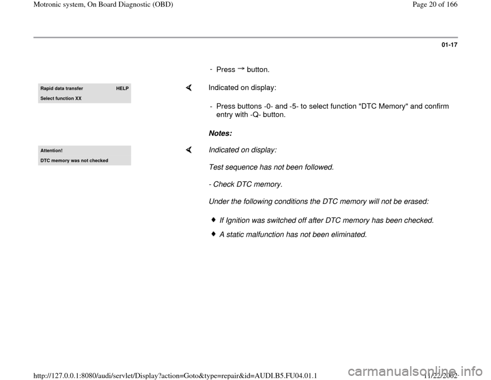
Press button.Rapid data transfer
HELP
Select function XX
Indicated on display:
Notes: - Press buttons -0- and -5- to select function "DTC Memory" and confirm
entry with -Q- button.
Attention!DTC memor
y was not checked
Indicated on display:
Test sequence has not been followed.
- Check DTC memory.
Under the following conditions the DTC memory will not be erased:
If Ignition was switched off after DTC memory has been checked.A static malfunction has not been eliminated.
Pa
ge 20 of 166 Motronic s
ystem, On Board Dia
gnostic
(OBD
)
11/22/2002 htt
p://127.0.0.1:8080/audi/servlet/Dis
play?action=Goto&t
yp
e=re
pair&id=AUDI.B5.FU04.01.1
Page 21 of 166
01-18
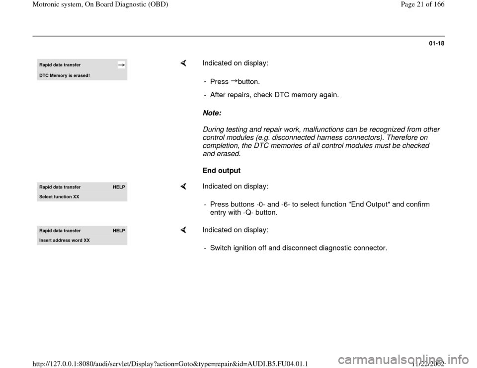
Rapid data transfer DTC Memor
y is erased!
Indicated on display:
Note:
During testing and repair work, malfunctions can be recognized from other
control modules (e.g. disconnected harness connectors). Therefore on
completion, the DTC memories of all control modules must be checked
and erased.
End output -
Press button.- After repairs, check DTC memory again.
Rapid data transfer
HELP
Select function XX
Indicated on display:
- Press buttons -0- and -6- to select function "End Output" and confirm
entry with -Q- button.
Rapid data transfer
HELP
Insert address word XX
Indicated on display:
- Switch ignition off and disconnect diagnostic connector.
Pa
ge 21 of 166 Motronic s
ystem, On Board Dia
gnostic
(OBD
)
11/22/2002 htt
p://127.0.0.1:8080/audi/servlet/Dis
play?action=Goto&t
yp
e=re
pair&id=AUDI.B5.FU04.01.1
Page 58 of 166

01-48
DTC
Description of malfunction
Corrective action
SAE
VAG
P1355 17763 Cyl. 1, ignition circuit
Open Circuit
2) - Check activation of power output stages Page 28
-11
P1356 17764 Cyl. 1, ignition circuit
Short to B+
2)
P1357 17765 Cyl. 1, ignition circuit
Short to ground
2)
P1358 17766 Cyl. 2, ignition circuit
Open Circuit
2)
P1359 17767 Cyl. 2, ignition circuit
Short Circuit to B+
2)
P1360 17768 Cyl. 2, ignition circuit
Short Circuit to ground
2)
2) With this malfunction the exhaust Malfunction Indicator Light (MIL) is only switched on by the ECM, if the malfunction is
recognized after the engine has been restarted. Significance of MIL Page 01
-3 .
Pa
ge 58 of 166 Motronic s
ystem, On Board Dia
gnostic
(OBD
)
11/22/2002 htt
p://127.0.0.1:8080/audi/servlet/Dis
play?action=Goto&t
yp
e=re
pair&id=AUDI.B5.FU04.01.1