automatic transmission AUDI A4 2000 B5 / 1.G APB Engine Motronic Syst
[x] Cancel search | Manufacturer: AUDI, Model Year: 2000, Model line: A4, Model: AUDI A4 2000 B5 / 1.GPages: 166, PDF Size: 0.53 MB
Page 84 of 166
01-70
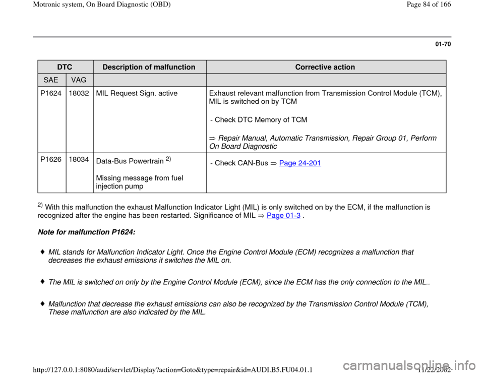
DTC
Description of malfunction
Corrective action
SAE
VAG
P1624 18032 MIL Request Sign. active Exhaust relevant malfunction from Transmission Control Module (TCM),
MIL is switched on by TCM
Repair Manual, Automatic Transmission, Repair Group 01, Perform
On Board Diagnostic - Check DTC Memory of TCM
P1626 18034
Data-Bus Powertrain
2)
Missing message from fuel
injection pump - Check CAN-Bus Page 24
-201
2) With this malfunction the exhaust Malfunction Indicator Light (MIL) is only switched on by the ECM, if the malfunction is
recognized after the engine has been restarted. Significance of MIL Page 01
-3 .
Note for malfunction P1624:
MIL stands for Malfunction Indicator Light. Once the Engine Control Module (ECM) recognizes a malfunction that
decreases the exhaust emissions it switches the MIL on.
The MIL is switched on only by the Engine Control Module (ECM), since the ECM has the only connection to the MIL..
Malfunction that decrease the exhaust emissions can also be recognized by the Transmission Control Module (TCM),
These malfunction are also indicated by the MIL.
Pa
ge 84 of 166 Motronic s
ystem, On Board Dia
gnostic
(OBD
)
11/22/2002 htt
p://127.0.0.1:8080/audi/servlet/Dis
play?action=Goto&t
yp
e=re
pair&id=AUDI.B5.FU04.01.1
Page 93 of 166
01-76
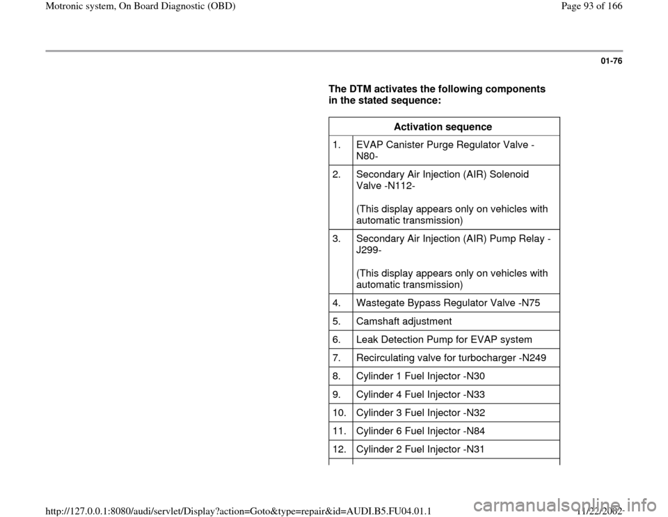
The DTM activates the following components
in the stated sequence:
Activation sequence
1. EVAP Canister Purge Regulator Valve -
N80-
2. Secondary Air Injection (AIR) Solenoid
Valve -N112-
(This display appears only on vehicles with
automatic transmission)
3. Secondary Air Injection (AIR) Pump Relay -
J299-
(This display appears only on vehicles with
automatic transmission)
4. Wastegate Bypass Regulator Valve -N75
5. Camshaft adjustment
6. Leak Detection Pump for EVAP system
7. Recirculating valve for turbocharger -N249
8. Cylinder 1 Fuel Injector -N30
9. Cylinder 4 Fuel Injector -N33
10. Cylinder 3 Fuel Injector -N32
11. Cylinder 6 Fuel Injector -N84
12. Cylinder 2 Fuel Injector -N31
Pa
ge 93 of 166 Motronic s
ystem, On Board Dia
gnostic
(OBD
)
11/22/2002 htt
p://127.0.0.1:8080/audi/servlet/Dis
play?action=Goto&t
yp
e=re
pair&id=AUDI.B5.FU04.01.1
Page 97 of 166
01-79
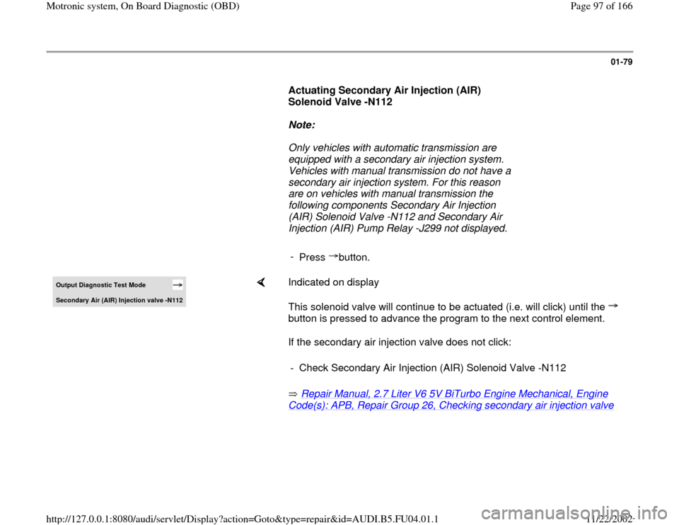
Actuating Secondary Air Injection (AIR)
Solenoid Valve -N112
Note:
Only vehicles with automatic transmission are
equipped with a secondary air injection system.
Vehicles with manual transmission do not have a
secondary air injection system. For this reason
are on vehicles with manual transmission the
following components Secondary Air Injection
(AIR) Solenoid Valve -N112 and Secondary Air
Injection (AIR) Pump Relay -J299 not displayed.
-
Press button.Output Diagnostic Test Mode Secondar
y Air
(AIR
) Injection valve -N112
Indicated on display
This solenoid valve will continue to be actuated (i.e. will click) until the
button is pressed to advance the program to the next control element.
If the secondary air injection valve does not click:
Repair Manual, 2.7 Liter V6 5V BiTurbo Engine Mechanical, Engine Code(s): APB, Repair Group 26, Checking secondary air injection valve
- Check Secondary Air Injection (AIR) Solenoid Valve -N112
Pa
ge 97 of 166 Motronic s
ystem, On Board Dia
gnostic
(OBD
)
11/22/2002 htt
p://127.0.0.1:8080/audi/servlet/Dis
play?action=Goto&t
yp
e=re
pair&id=AUDI.B5.FU04.01.1
Page 98 of 166
01-80
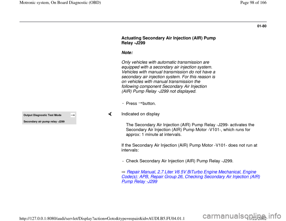
Actuating Secondary Air Injection (AIR) Pump
Relay -J299
Note:
Only vehicles with automatic transmission are
equipped with a secondary air injection system.
Vehicles with manual transmission do not have a
secondary air injection system. For this reason is
on vehicles with manual transmission the
following component Secondary Air Injection
(AIR) Pump Relay -J299 not displayed.
-
Press button.Output Diagnostic Test Mode Secondar
y air pump rela
y -J299
Indicated on display
If the Secondary Air Injection (AIR) Pump Motor -V101- does not run at
intervals:
Repair Manual, 2.7 Liter V6 5V BiTurbo Engine Mechanical, Engine Code(s): APB, Repair Group 26, Checking Secondary Air Injection (AIR) Pump Relay
-J299
The Secondary Air Injection (AIR) Pump Relay -J299- activates the
Secondary Air Injection (AIR) Pump Motor -V101-, which runs for
approx: 1 minute at intervals.
- Check Secondary Air Injection (AIR) Pump Relay -J299.
Pa
ge 98 of 166 Motronic s
ystem, On Board Dia
gnostic
(OBD
)
11/22/2002 htt
p://127.0.0.1:8080/audi/servlet/Dis
play?action=Goto&t
yp
e=re
pair&id=AUDI.B5.FU04.01.1
Page 106 of 166
01-88
Basic setting
With the ignition on and engine not running,
the following operation can be performed in
the "Basic setting" mode (function 04):
Adaptation of throttle valve control module to
ECM Page 24
-146
Vehicles with automatic transmission:
Adaptation of kick down function of accelerator
pedal position sensor to ECM Display group
63 ( Page 24
-166
)
With the engine running, the following
operations can be performed in the basic
setting mode "Function 04":
Learning process (adaptation) for oxygen
sensor control every display group
Troubleshooting by targeted activation and
deactivation of oxygen sensor control display
group 99 (Observe note on page Page 24
-
81
).
Pa
ge 106 of 166 Motronic s
ystem, On Board Dia
gnostic
(OBD
)
11/22/2002 htt
p://127.0.0.1:8080/audi/servlet/Dis
play?action=Goto&t
yp
e=re
pair&id=AUDI.B5.FU04.01.1
Page 114 of 166

01-94
Coding variations of Engine Control Module (ECM)
Country/
Emission standard Power train /
Additional systems Transmission
Type of
vehicle
00 = ------------------ 0 = ------------------ 0 = ------------------ 0 = ---------
---------
01 = ------------------ 1 = ------------------ 1 = 6-speed manual
transmission 1 = A4
02 = ------------------ 2 = ------------------ 2 = ------------------ 2 = ---------
---------
03 = ------------------ 3 = ------------------ 3 = ------------------ 3 = ---------
---------
04 = ------------------ 4 = ------------------ 4 = ------------------ 4 = ---------
---------
05 = ------------------- 5 = ------------------ 5 = 5-speed automatic
transmission (ZF)
(5HP24) 5 = ---------
---------
06 = USA; TLEV (Exhaust emission
standard) NOTE: Vehicles with Leak
Detection Pump (LDP) 6 = All-wheel drive without Anti Slip
Regulation (ASR)/Electronic Stability Program
(ESP) (with CAN-Bus system) 6 = ------------------ 6 = ---------
---------
07 = ----------------- 7 = All-wheel drive with Anti Slip Regulation
(ASR)/Electronic Stability Program (ESP)
(with CAN-Bus system) 7 = ------------------ 7 = ---------
---------
Notes:
Pa
ge 114 of 166 Motronic s
ystem, On Board Dia
gnostic
(OBD
)
11/22/2002 htt
p://127.0.0.1:8080/audi/servlet/Dis
play?action=Goto&t
yp
e=re
pair&id=AUDI.B5.FU04.01.1
Page 164 of 166
01-134
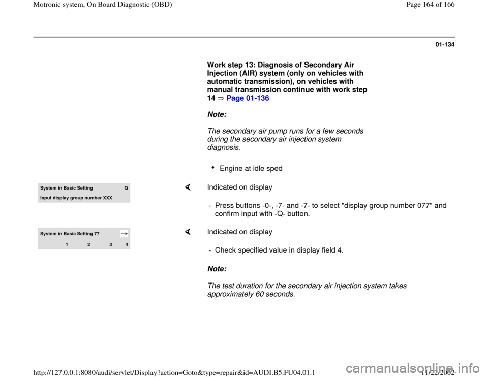
Work step 13: Diagnosis of Secondary Air
Injection (AIR) system (only on vehicles with
automatic transmission), on vehicles with
manual transmission continue with work step
14 Page 01
-136
Note:
The secondary air pump runs for a few seconds
during the secondary air injection system
diagnosis.
Engine at idle sped
System in Basic Setting
Q
Input displa
y group number XXX
Indicated on display
- Press buttons -0-, -7- and -7- to select "display group number 077" and
confirm input with -Q- button.
System in Basic Setting 77
1
2
3
4
Indicated on display
Note:
The test duration for the secondary air injection system takes
approximately 60 seconds. - Check specified value in display field 4.
Pa
ge 164 of 166 Motronic s
ystem, On Board Dia
gnostic
(OBD
)
11/22/2002 htt
p://127.0.0.1:8080/audi/servlet/Dis
play?action=Goto&t
yp
e=re
pair&id=AUDI.B5.FU04.01.1