AUDI A4 2000 B5 / 1.G APB Engine Valve Gear Service Workshop Manual
Manufacturer: AUDI, Model Year: 2000,
Model line: A4,
Model: AUDI A4 2000 B5 / 1.G
Pages: 99, PDF Size: 1.78 MB
AUDI A4 2000 B5 / 1.G APB Engine Valve Gear Service Workshop Manual
A4 2000 B5 / 1.G
AUDI
AUDI
https://www.carmanualsonline.info/img/6/969/w960_969-0.png
AUDI A4 2000 B5 / 1.G APB Engine Valve Gear Service Workshop Manual
Trending: coolant level, oil pressure, seats, check engine, clock, mileage, light
Page 1 of 99
15-1
Valve gear, servicing
Notes:
Cylinder heads which have cracks between the
valve seats or between valve seat inserts and
the spark plug thread can be used further
without reducing service life, provided the
cracks do not exceed a maximum of 0.3 mm in
width, or when no more than the first 4 turns of
the spark plug threads are cracked.
After installing new lifters the engine must not
be started for about 30 minutes (otherwise
valves will strike pistons). Turn crankshaft two
complete revolutions before starting.
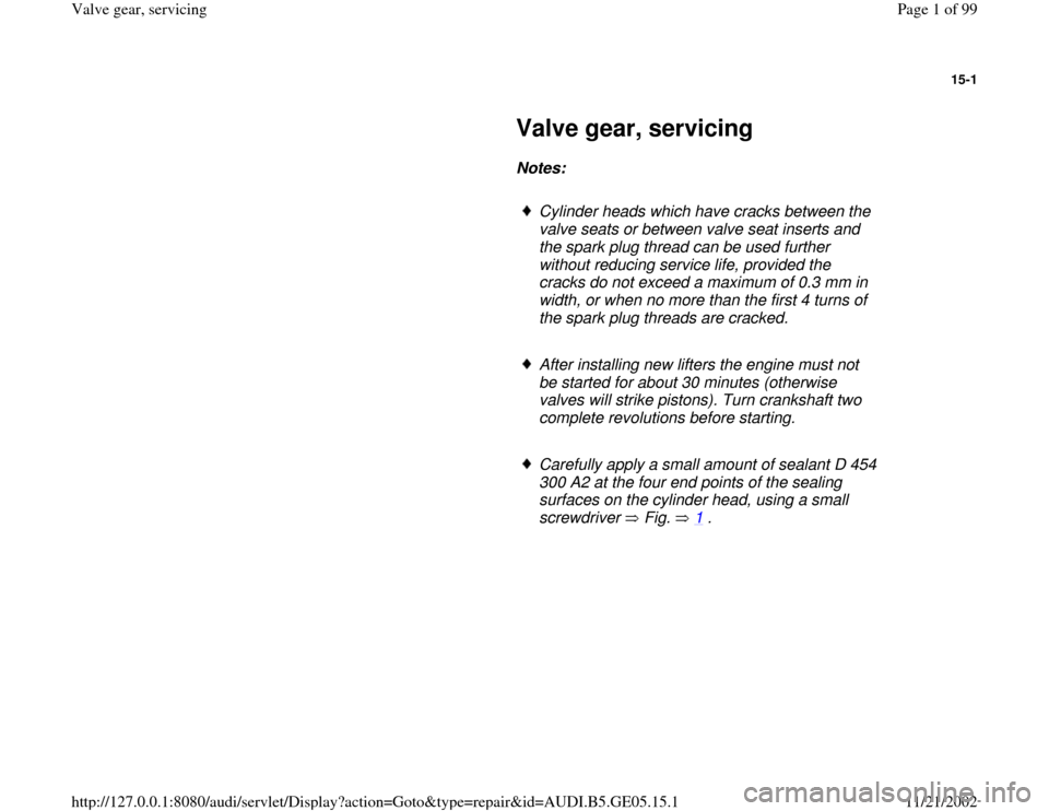
Carefully apply a small amount of sealant D 454
300 A2 at the four end points of the sealing
surfaces on the cylinder head, using a small
screwdriver Fig. 1
.
Pa
ge 1 of 99 Valve
gear, servicin
g
11/21/2002 htt
p://127.0.0.1:8080/audi/servlet/Dis
play?action=Goto&t
yp
e=re
pair&id=AUDI.B5.GE05.15.1
Page 2 of 99
15-2
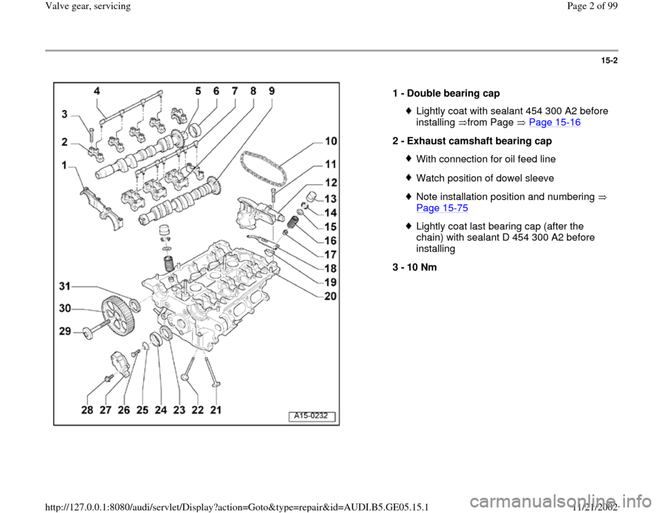
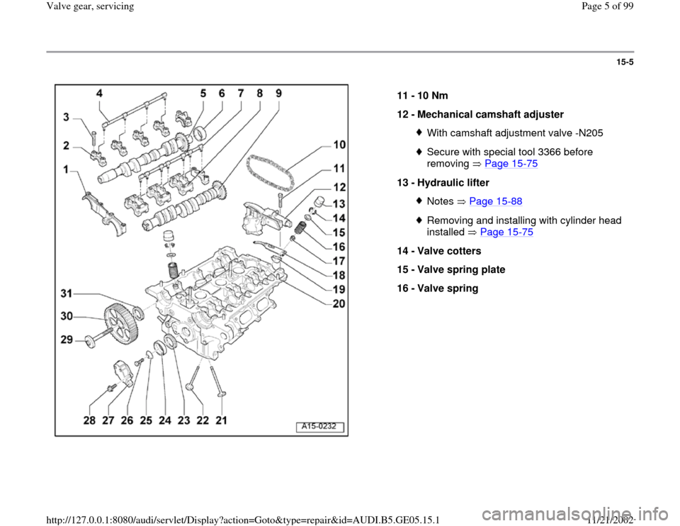
1 -
Double bearing cap
Lightly coat with sealant 454 300 A2 before
installing from Page Page 15
-16
2 -
Exhaust camshaft bearing cap
With connection for oil feed lineWatch position of dowel sleeveNote installation position and numbering
Page 15
-75
Lightly coat last bearing cap (after the
chain) with sealant D 454 300 A2 before
installing
3 -
10 Nm
Pa
ge 2 of 99 Valve
gear, servicin
g
11/21/2002 htt
p://127.0.0.1:8080/audi/servlet/Dis
play?action=Goto&t
yp
e=re
pair&id=AUDI.B5.GE05.15.1
Page 3 of 99
15-3
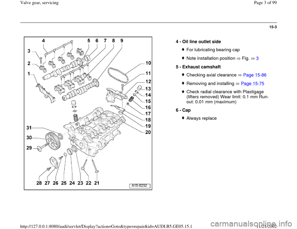
4 -
Oil line outlet side
For lubricating bearing capNote installation position Fig. 3
5 -
Exhaust camshaft
Checking axial clearance Page 15
-86
Removing and installing Page 15
-75
Check radial clearance with Plastigage
(lifters removed) Wear limit: 0.1 mm Run-
out: 0.01 mm (maximum)
6 -
Cap Always replace
Pa
ge 3 of 99 Valve
gear, servicin
g
11/21/2002 htt
p://127.0.0.1:8080/audi/servlet/Dis
play?action=Goto&t
yp
e=re
pair&id=AUDI.B5.GE05.15.1
Page 4 of 99
15-4
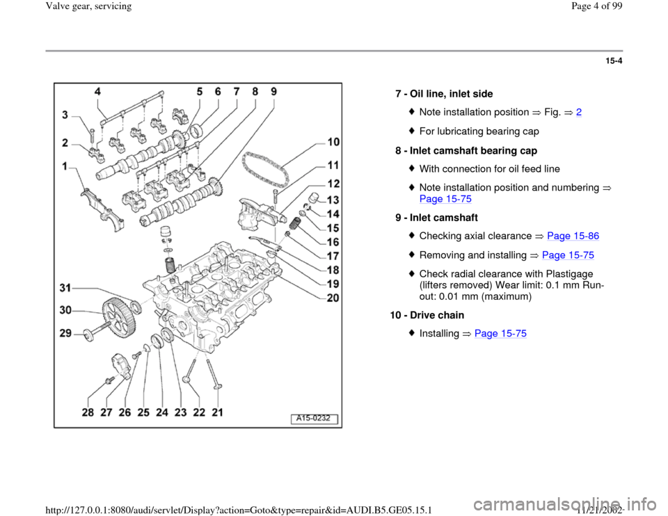
7 -
Oil line, inlet side
Note installation position Fig. 2For lubricating bearing cap
8 -
Inlet camshaft bearing cap With connection for oil feed lineNote installation position and numbering
Page 15
-75
9 -
Inlet camshaft
Checking axial clearance Page 15
-86
Removing and installing Page 15
-75
Check radial clearance with Plastigage
(lifters removed) Wear limit: 0.1 mm Run-
out: 0.01 mm (maximum)
10 -
Drive chain Installing Page 15
-75
Pa
ge 4 of 99 Valve
gear, servicin
g
11/21/2002 htt
p://127.0.0.1:8080/audi/servlet/Dis
play?action=Goto&t
yp
e=re
pair&id=AUDI.B5.GE05.15.1
Page 5 of 99
15-5
11 -
10 Nm
12 -
Mechanical camshaft adjuster
With camshaft adjustment valve -N205Secure with special tool 3366 before
removing Page 15
-75
13 -
Hydraulic lifter
Notes Page 15
-88
Removing and installing with cylinder head
installed Page 15
-75
14 -
Valve cotters
15 -
Valve spring plate
16 -
Valve spring
Pa
ge 5 of 99 Valve
gear, servicin
g
11/21/2002 htt
p://127.0.0.1:8080/audi/servlet/Dis
play?action=Goto&t
yp
e=re
pair&id=AUDI.B5.GE05.15.1
Page 6 of 99
15-6
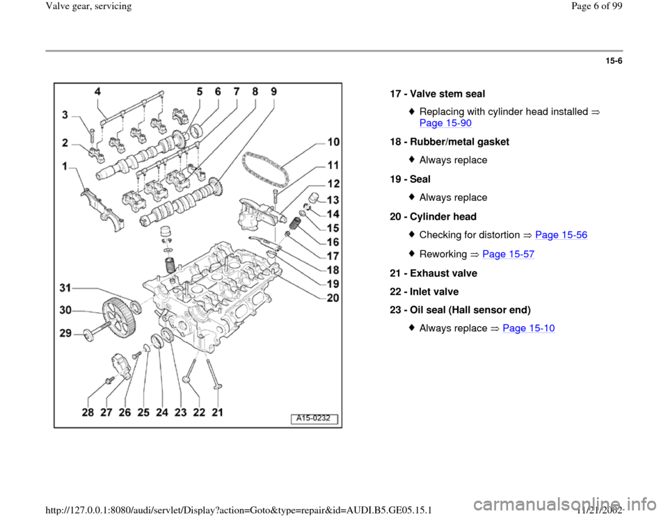
17 -
Valve stem seal
Replacing with cylinder head installed
Page 15
-90
18 -
Rubber/metal gasket
Always replace
19 -
Seal Always replace
20 -
Cylinder head Checking for distortion Page 15
-56
Reworking Page 15
-57
21 -
Exhaust valve
22 -
Inlet valve
23 -
Oil seal (Hall sensor end)
Always replace Page 15
-10
Pa
ge 6 of 99 Valve
gear, servicin
g
11/21/2002 htt
p://127.0.0.1:8080/audi/servlet/Dis
play?action=Goto&t
yp
e=re
pair&id=AUDI.B5.GE05.15.1
Page 7 of 99
15-7
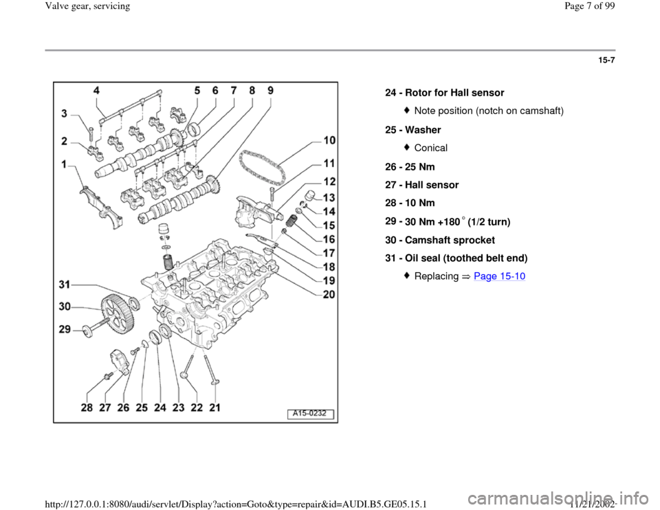
24 -
Rotor for Hall sensor
Note position (notch on camshaft)
25 -
Washer Conical
26 -
25 Nm
27 -
Hall sensor
28 -
10 Nm
29 -
30 Nm +180 (1/2 turn)
30 -
Camshaft sprocket
31 -
Oil seal (toothed belt end)
Replacing Page 15
-10
Pa
ge 7 of 99 Valve
gear, servicin
g
11/21/2002 htt
p://127.0.0.1:8080/audi/servlet/Dis
play?action=Goto&t
yp
e=re
pair&id=AUDI.B5.GE05.15.1
Page 8 of 99
15-8
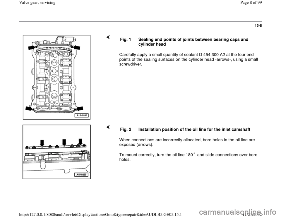
Carefully apply a small quantity of sealant D 454 300 A2 at the four end
points of the sealing surfaces on the cylinder head -arrows-, using a small
screwdriver. Fig. 1 Sealing end points of joints between bearing caps and
cylinder head
When connections are incorrectly allocated, bore holes in the oil line are
exposed (arrows).
To mount correctly, turn the oil line 180 and slide connections over bore
holes. Fig. 2 Installation position of the oil line for the inlet camshaft
Pa
ge 8 of 99 Valve
gear, servicin
g
11/21/2002 htt
p://127.0.0.1:8080/audi/servlet/Dis
play?action=Goto&t
yp
e=re
pair&id=AUDI.B5.GE05.15.1
Page 9 of 99
15-9
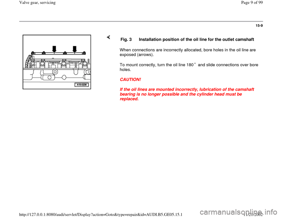
When connections are incorrectly allocated, bore holes in the oil line are
exposed (arrows).
To mount correctly, turn the oil line 180 and slide connections over bore
holes.
CAUTION!
If the oil lines are mounted incorrectly, lubrication of the camshaft
bearing is no longer possible and the cylinder head must be
replaced. Fig. 3 Installation position of the oil line for the outlet camshaft
Pa
ge 9 of 99 Valve
gear, servicin
g
11/21/2002 htt
p://127.0.0.1:8080/audi/servlet/Dis
play?action=Goto&t
yp
e=re
pair&id=AUDI.B5.GE05.15.1
Page 10 of 99
15-10
Oil seals in cylinder heads, replacing
Oil seal for camshaft drive (left and right
cylinder heads)
Note:
If the oil seal on one side is leaking it is advisable
to replace the seals on both sides.
- Remove ribbed belt Page 13
-1 .
- Remove toothed belt Page 13
-4 .
- Remove rear toothed belt guard.
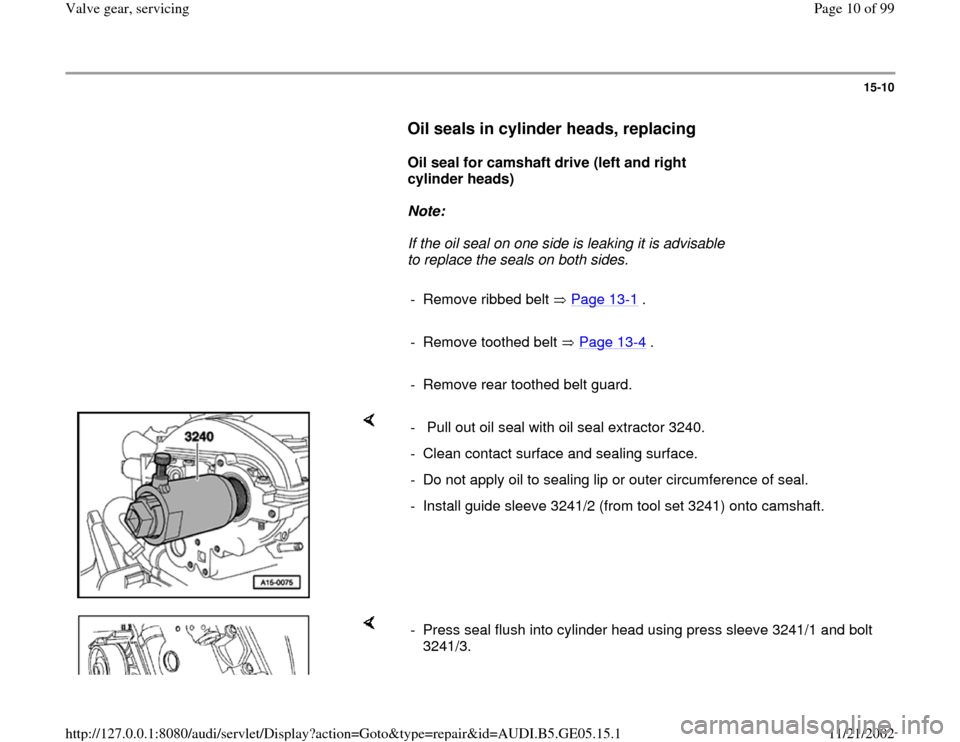
- Pull out oil seal with oil seal extractor 3240.
- Clean contact surface and sealing surface.
- Do not apply oil to sealing lip or outer circumference of seal.
- Install guide sleeve 3241/2 (from tool set 3241) onto camshaft.
- Press seal flush into cylinder head using press sleeve 3241/1 and bolt
3241/3.
Pa
ge 10 of 99 Valve
gear, servicin
g
11/21/2002 htt
p://127.0.0.1:8080/audi/servlet/Dis
play?action=Goto&t
yp
e=re
pair&id=AUDI.B5.GE05.15.1
Trending: engine oil, light, check engine light, battery, wiring, check oil, warning light
