wiring diagram AUDI A4 2000 B5 / 1.G APB Engine Motronic Syst
[x] Cancel search | Manufacturer: AUDI, Model Year: 2000, Model line: A4, Model: AUDI A4 2000 B5 / 1.GPages: 166, PDF Size: 0.53 MB
Page 4 of 166
01-4
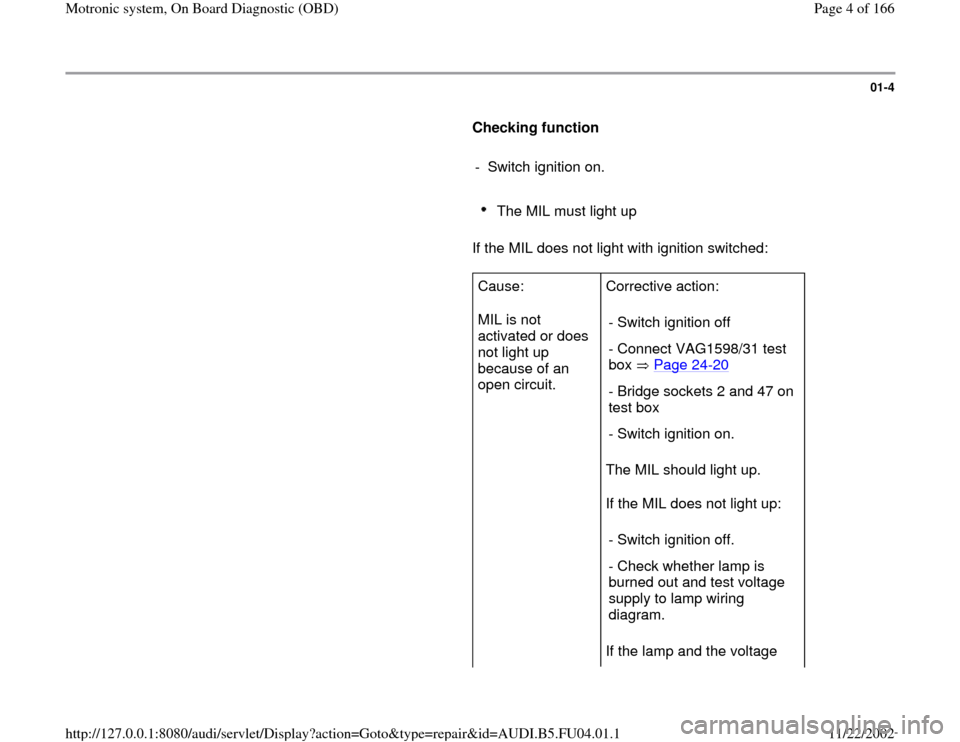
Checking function
- Switch ignition on.
The MIL must light up
If the MIL does not light with ignition switched:
Cause:
MIL is not
activated or does
not light up
because of an
open circuit. Corrective action:
The MIL should light up.
If the MIL does not light up:
If the lamp and the voltage - Switch ignition off
- Connect VAG1598/31 test
box Page 24
-20
- Bridge sockets 2 and 47 on
test box
- Switch ignition on.
- Switch ignition off.
- Check whether lamp is
burned out and test voltage
supply to lamp wiring
diagram.
Pa
ge 4 of 166 Motronic s
ystem, On Board Dia
gnostic
(OBD
)
11/22/2002 htt
p://127.0.0.1:8080/audi/servlet/Dis
play?action=Goto&t
yp
e=re
pair&id=AUDI.B5.FU04.01.1
Page 5 of 166
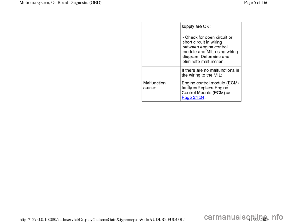
supply are OK:
- Check for open circuit or
short circuit in wiring
between engine control
module and MIL using wiring
diagram. Determine and
eliminate malfunction.
If there are no malfunctions in
the wiring to the MIL:
Malfunction
cause: Engine control module (ECM)
faulty Replace Engine
Control Module (ECM)
Page 24
-24
.
Pa
ge 5 of 166 Motronic s
ystem, On Board Dia
gnostic
(OBD
)
11/22/2002 htt
p://127.0.0.1:8080/audi/servlet/Dis
play?action=Goto&t
yp
e=re
pair&id=AUDI.B5.FU04.01.1
Page 7 of 166
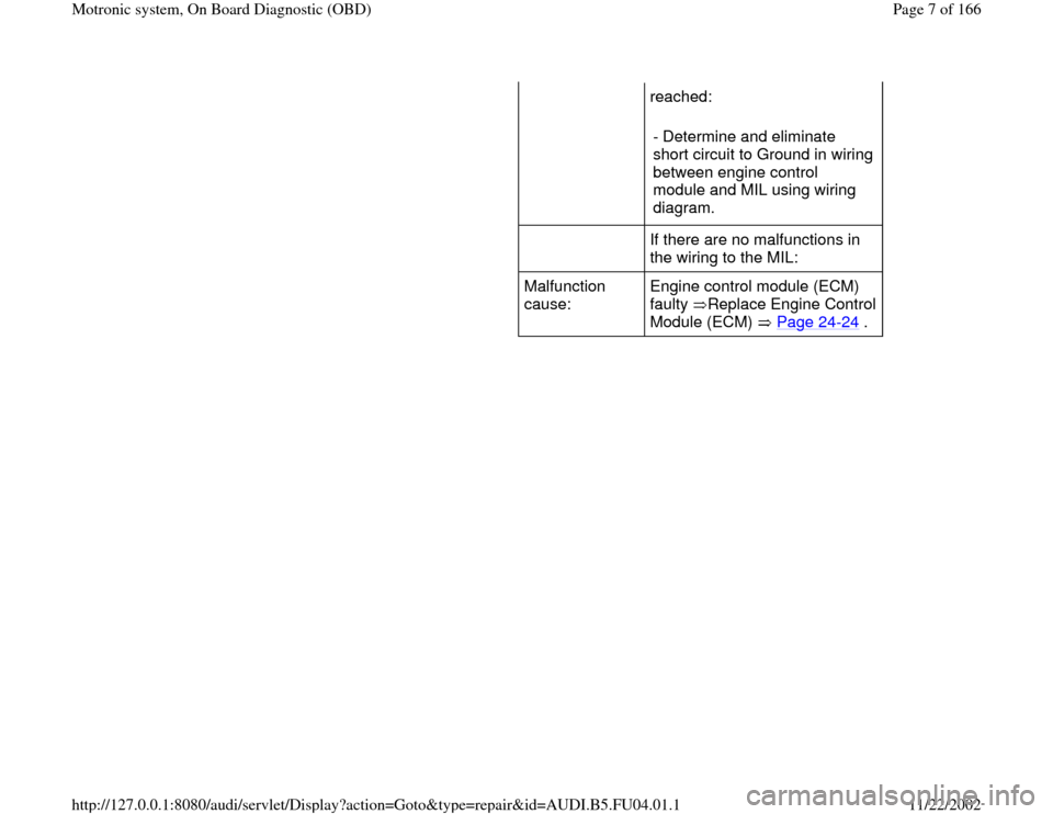
reached:
- Determine and eliminate
short circuit to Ground in wiring
between engine control
module and MIL using wiring
diagram.
If there are no malfunctions in
the wiring to the MIL:
Malfunction
cause: Engine control module (ECM)
faulty Replace Engine Control
Module (ECM) Page 24
-24
.
Pa
ge 7 of 166 Motronic s
ystem, On Board Dia
gnostic
(OBD
)
11/22/2002 htt
p://127.0.0.1:8080/audi/servlet/Dis
play?action=Goto&t
yp
e=re
pair&id=AUDI.B5.FU04.01.1
Page 13 of 166
01-11
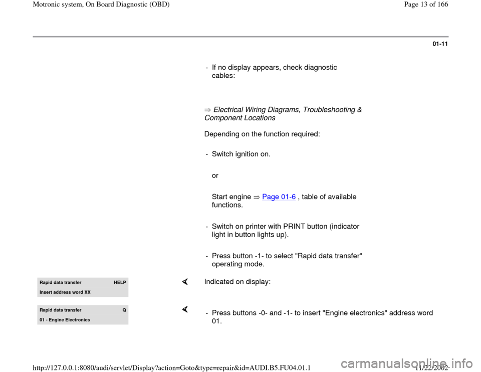
- If no display appears, check diagnostic
cables:
Electrical Wiring Diagrams, Troubleshooting &
Component Locations Depending on the function required:
- Switch ignition on.
or
Start engine Page 01
-6 , table of available
functions.
- Switch on printer with PRINT button (indicator
light in button lights up).
- Press button -1- to select "Rapid data transfer"
operating mode. Rapid data transfer
HELP
Insert address word XX
Indicated on display:
Rapid data transfer
Q
01 - En
gine Electronics
- Press buttons -0- and -1- to insert "Engine electronics" address word
01.
Pa
ge 13 of 166 Motronic s
ystem, On Board Dia
gnostic
(OBD
)
11/22/2002 htt
p://127.0.0.1:8080/audi/servlet/Dis
play?action=Goto&t
yp
e=re
pair&id=AUDI.B5.FU04.01.1
Page 15 of 166
01-12
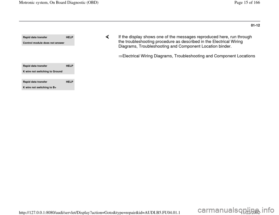
Rapid data transfer
HELP
Control module does not answer
If the display shows one of the messages reproduced here, run through
the troubleshooting procedure as described in the Electrical Wiring
Diagrams, Troubleshooting and Component Location binder.
Electrical Wiring Diagrams, Troubleshooting and Component Locations
Rapid data transfer
HELP
K wire not switching to Ground
Rapid data transfer
HELP
K wire not switching to B+
Pa
ge 15 of 166 Motronic s
ystem, On Board Dia
gnostic
(OBD
)
11/22/2002 htt
p://127.0.0.1:8080/audi/servlet/Dis
play?action=Goto&t
yp
e=re
pair&id=AUDI.B5.FU04.01.1
Page 22 of 166
01-19
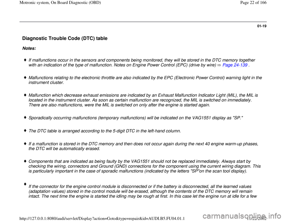
Diagnostic Trouble Code (DTC) table
Notes:
If malfunctions occur in the sensors and components being monitored, they will be stored in the DTC memory together
with an indication of the type of malfunction. Notes on Engine Power Control (EPC) (drive by wire) Page 24
-139
.
Malfunctions relating to the electronic throttle are also indicated by the EPC (Electronic Power Control) warning light in the
instrument cluster.
Malfunction which decrease exhaust emissions are indicated by an Exhaust Malfunction Indicator Light (MIL), the MIL is
located in the instrument cluster. As soon as certain malfunction are recognized, the MIL is switched on immediately.
There are also malfunctions, were the MIL is switched on only after the engine is started again.
Sporadically occurring malfunctions (temporary malfunctions) will be indicated on the VAG1551 display as "SP."
The DTC table is arranged according to the 5-digit DTC in the left-hand column.
If a malfunction is stored in the DTC memory and then does not occur again during the next 40 engine warm-up phases,
the DTC will be automatically erased.
Components that are indicated as being faulty by the VAG1551 should not be replaced immediately. Always start by
checking the wiring, connectors and Ground (GND) connections for the component using the current wiring diagram. This
is particularly important in the case of sporadic malfunctions (indicated by the letters "SP"on the scan tool display).
If the connector for the engine control module is disconnected or if the battery is disconnected, all the learned values
(adaptation values) stored in the control module will be erased, although the contents of the DTC memory will remain
intact. The next time the engine is started the idling may be rough at first. In this case let the engine run at idle for a few
Pa
ge 22 of 166 Motronic s
ystem, On Board Dia
gnostic
(OBD
)
11/22/2002 htt
p://127.0.0.1:8080/audi/servlet/Dis
play?action=Goto&t
yp
e=re
pair&id=AUDI.B5.FU04.01.1
Page 71 of 166
01-59
DTC
Description of malfunction
Corrective
SAE
VAG
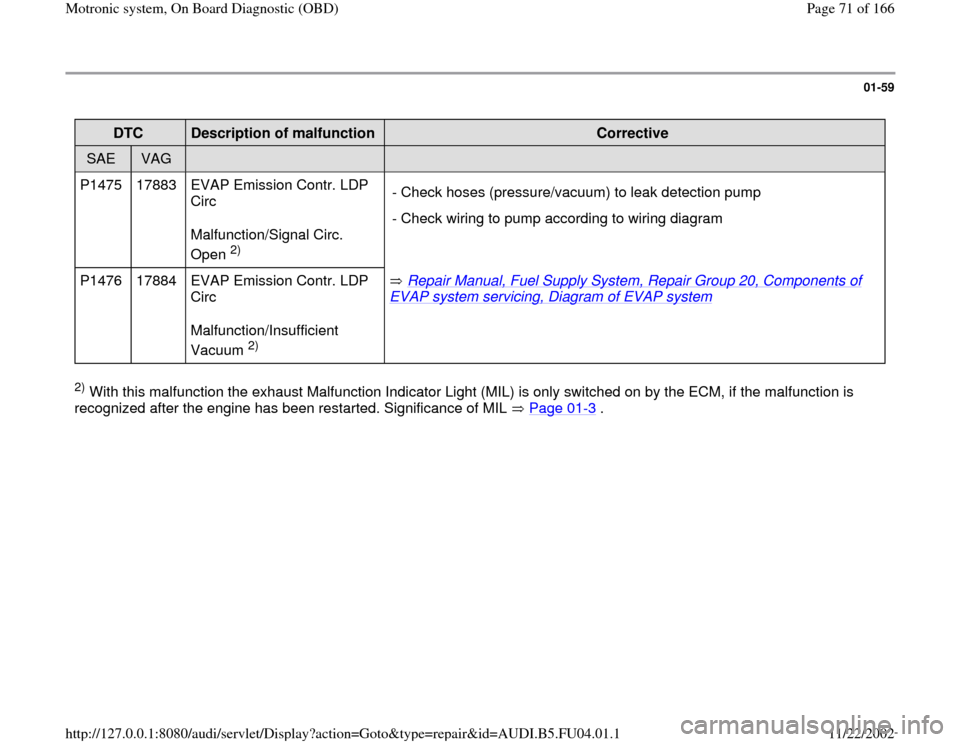
P1475 17883 EVAP Emission Contr. LDP
Circ
Malfunction/Signal Circ.
Open
2) - Check hoses (pressure/vacuum) to leak detection pump
- Check wiring to pump according to wiring diagram
P1476 17884 EVAP Emission Contr. LDP
Circ
Malfunction/Insufficient
Vacuum 2) Repair Manual, Fuel Supply System, Repair Group 20, Components of
EVAP system servicing, Diagram of EVAP system
2) With this malfunction the exhaust Malfunction Indicator Light (MIL) is only switched on by the ECM, if the malfunction is
recognized after the engine has been restarted. Significance of MIL Page 01
-3 .
Pa
ge 71 of 166 Motronic s
ystem, On Board Dia
gnostic
(OBD
)
11/22/2002 htt
p://127.0.0.1:8080/audi/servlet/Dis
play?action=Goto&t
yp
e=re
pair&id=AUDI.B5.FU04.01.1
Page 82 of 166
01-68
DTC
Description of
malfunction
Corrective action
SAE
VAG
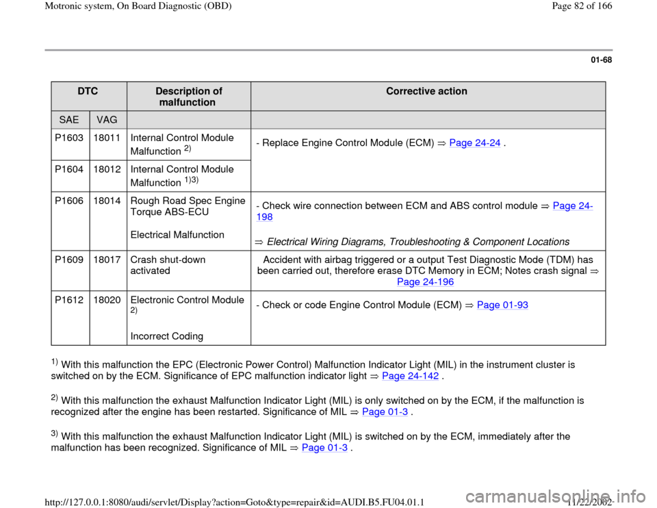
P1603 18011 Internal Control Module
Malfunction
2) - Replace Engine Control Module (ECM) Page 24
-24
.
P1604 18012 Internal Control Module
Malfunction
1)3)
P1606 18014 Rough Road Spec Engine
Torque ABS-ECU
Electrical Malfunction
Electrical Wiring Diagrams, Troubleshooting & Component Locations - Check wire connection between ECM and ABS control module Page 24
-
198
P1609 18017 Crash shut-down
activated Accident with airbag triggered or a output Test Diagnostic Mode (TDM) has
been carried out, therefore erase DTC Memory in ECM; Notes crash signal
Page 24
-196
P1612 18020 Electronic Control Module
2)
Incorrect Coding - Check or code Engine Control Module (ECM) Page 01
-93
1) With this malfunction the EPC (Electronic Power Control) Malfunction Indicator Light (MIL) in the instrument cluster is
switched on by the ECM. Significance of EPC malfunction indicator light Page 24
-142
.
2) With this malfunction the exhaust Malfunction Indicator Light (MIL) is only switched on by the ECM, if the malfunction is
recognized after the engine has been restarted. Significance of MIL Page 01
-3 .
3) With this malfunction the exhaust Malfunction Indicator Light (MIL) is switched on by the ECM, immediately after the
malfunction has been recognized. Significance of MIL Page 01
-3 .
Pa
ge 82 of 166 Motronic s
ystem, On Board Dia
gnostic
(OBD
)
11/22/2002 htt
p://127.0.0.1:8080/audi/servlet/Dis
play?action=Goto&t
yp
e=re
pair&id=AUDI.B5.FU04.01.1